Apparatus for optically arranging surface of alignment film and method for manufacturing liquid crystal display device using the same

a technology of alignment film and optical arrangement, which is applied in the direction of optics, polarising elements, instruments, etc., can solve the problems of difficult fabrication of polarizers, and achieve the effects of reducing the amount of transmitted light, reducing the amount of light irradiated on work 100, and large light loss

Inactive Publication Date: 2011-02-22
PANASONIC LIQUID CRYSTAL DISPLAY CO LTD +1
View PDF12 Cites 0 Cited by
  • Summary
  • Abstract
  • Description
  • Claims
  • Application Information

AI Technical Summary

Benefits of technology

[0021]In addition, when the number of glass plate 13 increases, the number of glass substrates through which light passes increases, and therefore, the amount of transmitted light decreases, and the amount of light irradiated on work 100 decreases (large light loss).
[0022]Consequently, in order to obtain the irradiation energy necessary for photo-induced alignment, the output of light source (lamp 1) must be greatly increased or irradiated beams must be converged, and increased apparatus cost and reduced irradiation region, or increased irradiation time due to small energy cause problems of reduced throughputs of photo-aligned process.
[0023]Therefore, it is an object of the present invention to provide a technique to efficiently separate polarized light of a desired wavelength from non-polarized light in the photo-aligned process in liquid crystal display elements.
[0026]That is, in the method of manufacturing the liquid crystal display element and the apparatus for optically arranging surface of alignment film according to the present invention, grating is utilized as a polarizer. In this polarizer, grating is used to separate polarized light from non-polarized light and the polarizer has protrusions and recesses of the material that fits to the desired wavelength (SiO2: silicon dioxide; CaF2: calcium fluoride; MgF2: magnesium fluoride, etc.), shape (quadrangle, triangle, circle, etc.), and size (height, width, length, intervals, etc.) formed on a substrate such as silica glass, etc. that transmit ultraviolet light, and by appropriately providing an incident angle, the polarizer provides the light-polarizing performance.
[0028]By using grating for the polarizer, it is possible to efficiently separate the polarized light of the desired wavelength from non-polarized light. In addition, by using the grating for the apparatus for optically arranging surface of alignment film, it is possible to downsize the polarized light forming section and furthermore, to provide the grating with the polarizer function at an irradiation energy loss (light loss) smaller than that of the method using the Brewster angle. Furthermore, by using the grating, it is possible to uniformly irradiate the whole light-irradiated region with the polarized light necessary for photo-induced alignment.
[0031]By using the grating as a polarizer, it is possible to separate polarized light of a desired wavelength at high efficiency.

Problems solved by technology

This polarizer is difficult to be fabricated because of the limitation in size of the evaporation apparatus when the optical interference film is used.

Method used


Image

  • Apparatus for optically arranging surface of alignment film and method for manufacturing liquid crystal display device using the same
  • Apparatus for optically arranging surface of alignment film and method for manufacturing liquid crystal display device using the same
  • Apparatus for optically arranging surface of alignment film and method for manufacturing liquid crystal display device using the same

Examples


Embodiment Construction

[0042]Referring now to the drawings, embodiments of the present invention will be described in detail hereinafter. By the way, like reference characters are assigned to like or corresponding members throughout all the drawings to explain the embodiments, and the repeated description is omitted.

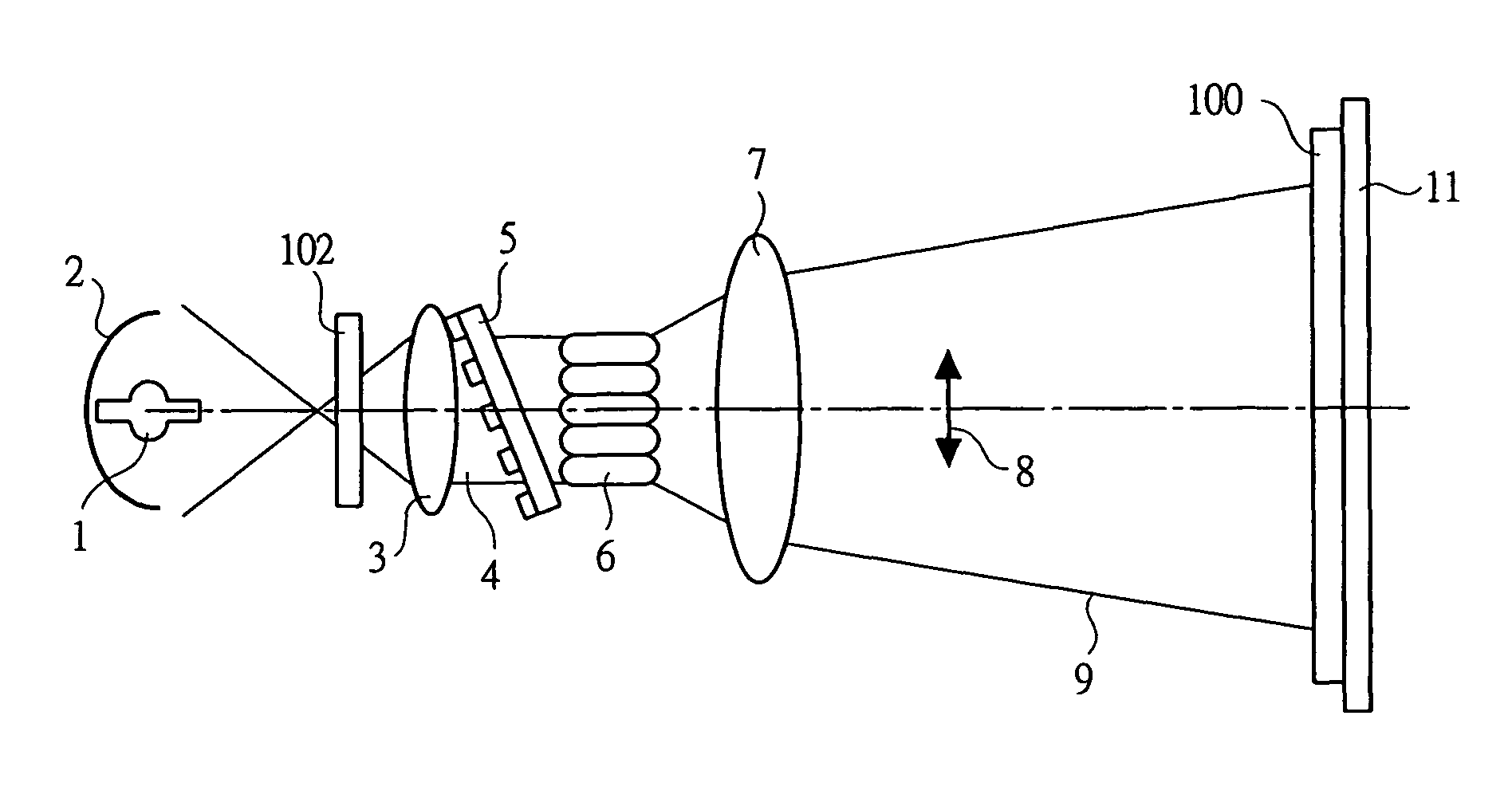
[0043]FIG. 1 generally illustrates configuration of an apparatus for optically arranging surface of alignment film according to one embodiment of the present invention.

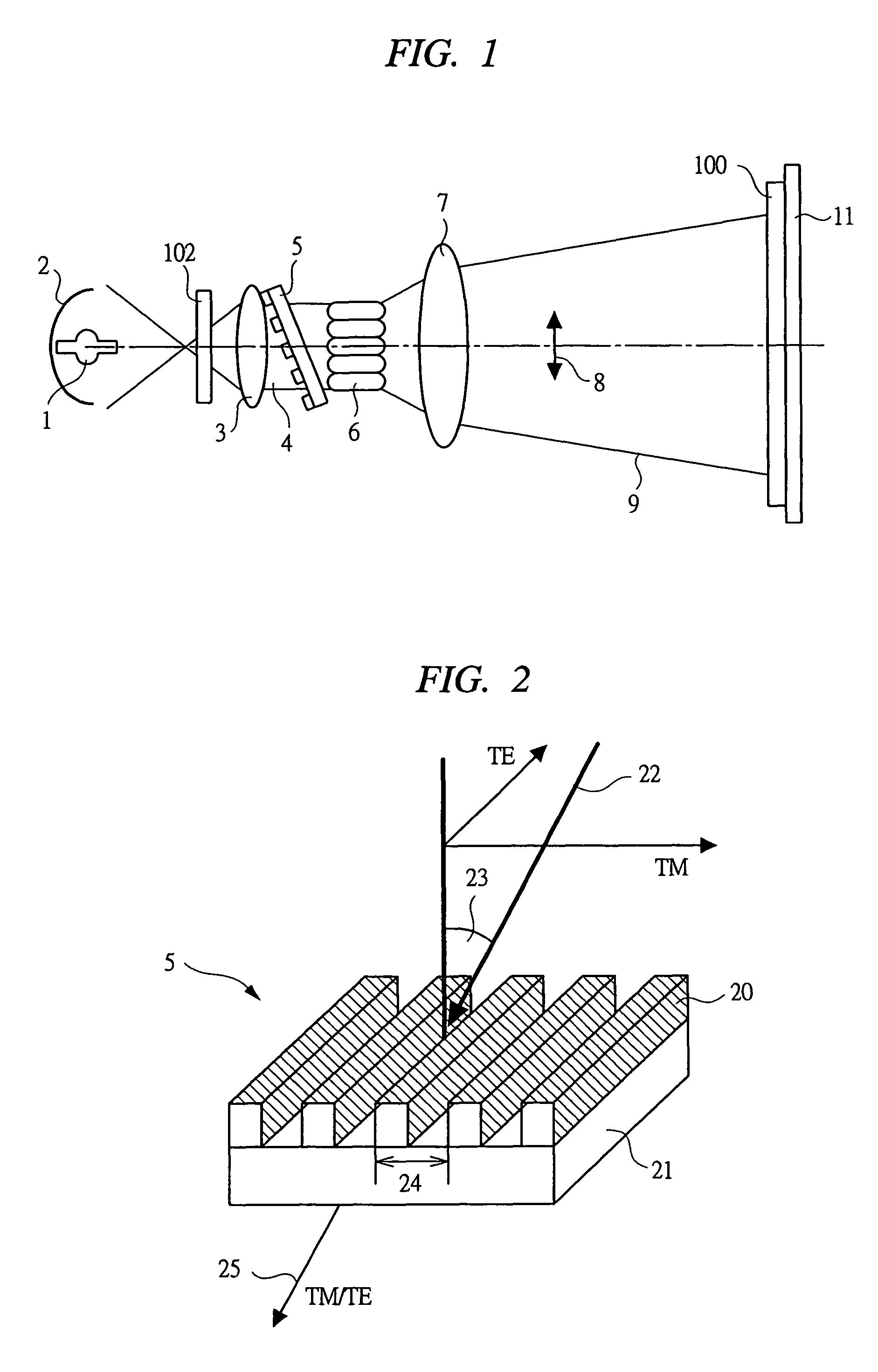
[0044]First of all, based on FIG. 1, one example of the apparatus for optically arranging surface of alignment film of the present embodiment is described. The apparatus for optically arranging surface of alignment film of the present embodiment is used for photo-aligned process, for example, in a liquid crystal display element, and comprises a lamp 1, condenser mirror 2, collimator lens 3, polarizer 5, integrator lens 6, diffusion lens 7, shutter 102, and others.

[0045]In FIG. 1, the lamp (light source) 1 is a Xe—Hg lamp, etc. t...


PUM

PropertyMeasurementUnit
sizeaaaaaaaaaa
sizeaaaaaaaaaa
incident angleaaaaaaaaaa

Abstract

Work is irradiated with polarized light generated by configuring in such a manner as to have a polarizer using a grating that separates polarized light from non-polarized light, a lamp and a condenser mirror that allow light to fall on the polarizer, a collimator lens that converts the incoming light into parallel beams, an integrator lens that uniformizes intensity distribution of light radiated from the polarizer, and a diffusion lens with functions to enlarge or contract the irradiated range to the work size, and by forming protrusions and recesses of the shape, material, and size that fit to the desired wavelength on a substrate such as quartz, etc. that transmit ultraviolet light, and by providing the light-polarizing performance by appropriately providing an incident angle. By carrying out this processing, the alignment film in the liquid crystal display element can be photo-aligned at high accuracy and uniformly.

Description

CROSS-REFERENCE TO RELATED APPLICATION[0001]The present application claims priority from Japanese Patent Application No. JP 2004-116518 filed on Apr. 12, 2004, the content of which is hereby incorporated by reference into this application.TECHNICAL FIELD OF THE INVENTION[0002]The present invention relates to a method for manufacturing liquid crystal display element and an apparatus for optically arranging surface of alignment film, and in particular, to a technique of irradiating liquid crystal display element composing alignment film with polarized light and controlling liquid crystal alignment (photo-induced alignment technique).BACKGROUND OF THE INVENTION[0003]As a device to display various images including still images and moving pictures such as PC (personal computer), TV (TV receiver), and others, liquid crystal display devices are popularly used. This kind of liquid crystal display devices are classified into a system to compose a liquid crystal panel of a construction in whi...

Claims


Application Information

Patent Timeline
Patent Type & Authority Patents(United States)
IPC IPC(8): G02F1/1337G02B5/30G02B27/28G02F1/1347
CPCG02B27/28G02F1/133788
Inventor ARAI, TAKESHIYOSHITAKE, YASUHIROMATSUYAMA, SHIGERU
Owner PANASONIC LIQUID CRYSTAL DISPLAY CO LTD
Why Eureka
Try Eureka