Quantum cryptographic communication apparatus

a communication apparatus and quantum cryptography technology, applied in the field of quantum cryptographic equipment, can solve problems such as adverse influences

Inactive Publication Date: 2011-02-22
MITSUBISHI ELECTRIC CORP
View PDF5 Cites 38 Cited by
  • Summary
  • Abstract
  • Description
  • Claims
  • Application Information

AI Technical Summary

Problems solved by technology

However, in the quantum cryptographic communication apparatus having the above-explained structure, the below-mentioned two fluctuation effects may give adverse influences which cannot be neglected.
As a result, there is such a problem in that even when only the photon pulses in the returning path are tried to be phase-modulated, the photon pulses in the going path are also phase-modulated which do not require such the phase modulation, depending upon a selected repetition frequency.

Method used


Image

  • Quantum cryptographic communication apparatus
  • Quantum cryptographic communication apparatus
  • Quantum cryptographic communication apparatus

Examples


embodiment 1

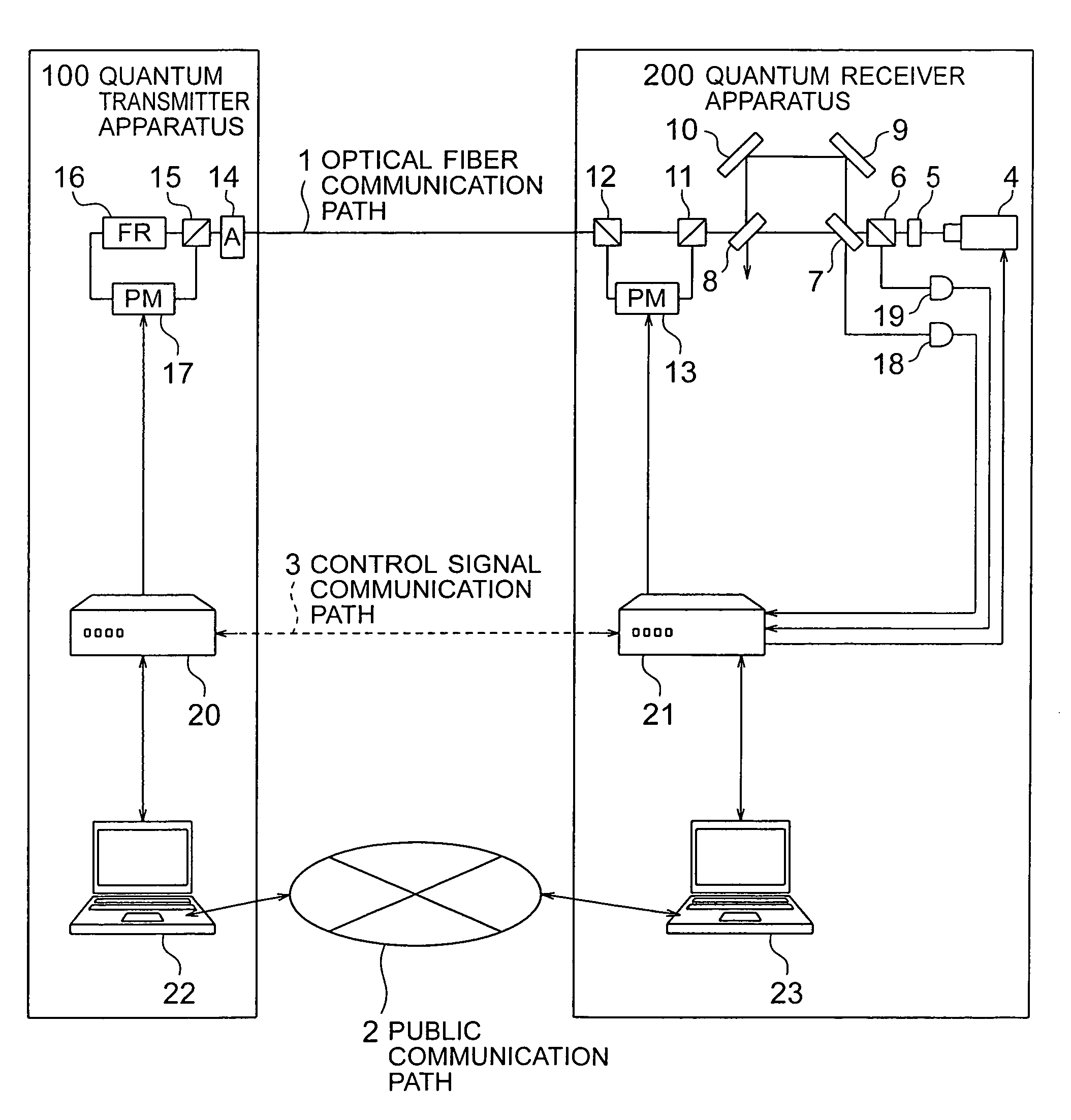
FIG. 1 is a structural diagram of a quantum cryptographic communication apparatus according to Embodiment 1 of the present invention, and represents an entire structure of the apparatus with employment of a phase modulating system based upon an optical fiber.

The quantum cryptographic communication apparatus shown in FIG. 1 includes a quantum transmitter apparatus 100 on a transmission side, a quantum receiver apparatus 200 on a reception side, an optical fiber communication path 1 which constitutes a quantum transmission path used to connect the quantum transmitter apparatus 100 to the quantum receiver apparatus 200 with each other, a public communication path 2, and a control signal communication path 3.

The quantum transmitter apparatus 100 and the quantum receiver apparatus 200 are connected with each other via the optical fiber communication path 1, the public communication path 2, and the control signal communication path 3. The optical fiber communication path 1 transfers photo...

embodiment 2

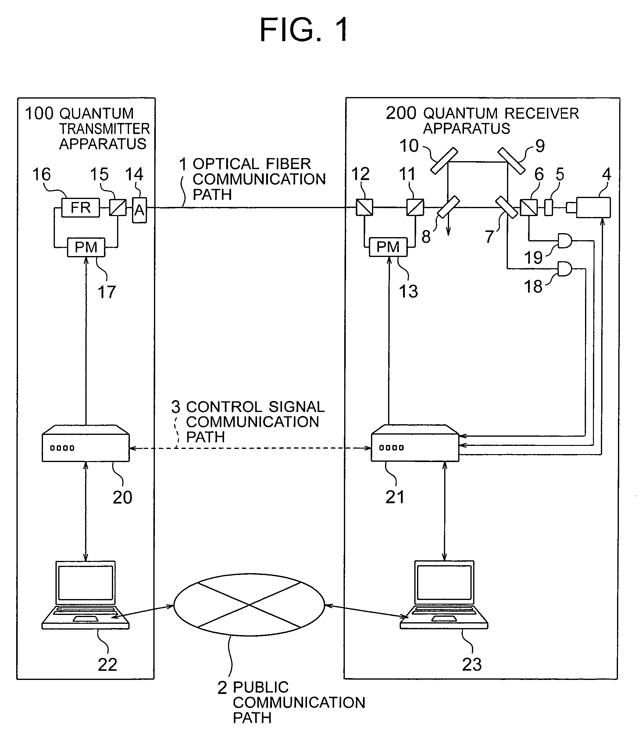
In the above-explained Embodiment 1, since the polarization planes of the twin photon pulses match with each other, only the polarization beam splitters 11 and 12 are used to realize the bypass optical circuit in which the phase modulator 13 is arranged. Embodiment 2 discloses a case of realizing a bypass optical circuit in which a phase modulator is arranged by using polarization beam splitters and a polarization modulator, in the case where polarization planes of twin photon pulses do not match with each other as in the optical systems described in Patent Documents 1 and 3, and Non-patent Document 1.

FIG. 5 is a structural diagram representing a quantum cryptographic communication apparatus according to Embodiment 2 of the present invention which includes a quantum receiver apparatus 200 provided with a polarization modulator 9 therein. In FIG. 5, a quantum transmitter apparatus 100 has a similar structure to the optical system described in Patent Document 3, and is provided with a...


PUM

PropertyMeasurementUnit
angleaaaaaaaaaa
angleaaaaaaaaaa
timeaaaaaaaaaa

Abstract

Provided is a quantum cryptography communication apparatus capable of preventing a go photon pulse from being phase modulated and also capable of freely selecting any repetitive frequency of a light source. In the quantum cryptography communication apparatus, a quantum receiver apparatus includes: a light source; an optical path loop having a multiplexing / interfering means for generating time difference twin photon pulses from the photon pulses of the light source and for multiplexing and causing interference between a signal optical pulse corresponding to a retrograde quantum and a reference optical pulse; a bypass optical path having a phase modulator for phase modulating only the received reference optical pulse; and a photon detector for observing the interfered light passed through the optical path loop, and a quantum transmitter apparatus includes: a polarized wave rotating means for rotating polarization planes of the twin photon pulses at a right angle in a non-reciprocal manner; a phase modulator for phase modulating and returning the signal optical pulse passed through the polarized wave rotating means, to the quantum receiver apparatus; and a beam attenuating means.

Description

TECHNICAL FIELDThe present invention relates to a quantum cryptographic apparatus for sharing secret information in quantum cryptography of a phase modulating system by causing a quantum to be modulated by secret information on a transmitter side and transmitted, and further causing the quantum received on a receiver side to be demodulated.BACKGROUND ARTA quantum cryptographic communication implies a communication system for sharing secret information on a transmitter side and a receiver side, in which the transmitter side modulates quanta, generally speaking, photons based upon the secret information and then transfers the modulated photons, and then, the receiver side demodulates the received quanta. Security of the secret information modulated on the quanta is guaranteed based upon the uncertainty principle of quantum mechanism. It should be noted that since quanta can be easily destroyed and all of information cannot be firmly transferred, random number information is employed a...

Claims


Application Information

Patent Timeline
Patent Type & Authority Patents(United States)
IPC IPC(8): H04L9/00H04L9/08H04L9/12H04L25/00G02F1/01H04B10/00H04B10/2507H04B10/532H04B10/548H04B10/70
CPCH04L9/0858H04B10/70
Inventor NISHIOKA, TSUYOSHIHASEGAWA, TOSHIOISHIZUKA, HIROKAZU
Owner MITSUBISHI ELECTRIC CORP
Why Eureka
Try Eureka