Fluid dispenser having infrared user sensor

a technology of infrared user and dispenser, which is applied in the direction of liquid transferring device, using reradiation, instruments, etc., can solve the problems of unplanned dispensing events, dispensers that employ this technology fail to compensate for changes in ambient lighting conditions, and present power requirements concerns

Active Publication Date: 2011-03-01
KANFER JOSEPH S
View PDF27 Cites 31 Cited by
  • Summary
  • Abstract
  • Description
  • Claims
  • Application Information

AI Technical Summary

Benefits of technology

[0008]It will be appreciated from the foregoing that there is a primary need for a low-cost hands-free dispensing system that operates at low power consumption and accounts for changes in lighting conditions.
[0011]It is a further aspect of the present invention to prevent continuous dispensing if the user or object remains in a target area.
[0015]The exemplary system disclosed herein fills these needs by facilitating a hands-free dispensing device that operates at low power consumption. The dispensing device utilizes an infrared light emitting diode (IR LED), a photodiode, and a controller that accounts for the presence of a user, and communicates the signal received to a dispense mechanism to provide fluid to a user. This dispensing device can be permanently affixed to the dispenser or can be incorporated within a replacement cartridge carried by the dispenser. This invention generally relates to the field of fluid dispensers, and it should be known that the following hands-free control circuitry could be easily adapted to apparatuses that dispense paper towels or other materials. One embodiment will be described as a soap dispenser, but it should be readily apparent that the present invention may also be applied to a variety of dispensers, which may dispense other fluids or paper products.

Problems solved by technology

However, dispensers that employ this technology fail to compensate for changes in ambient lighting conditions.
In addition, these dispensers present power requirement concerns, because detection circuitry requires constant power.
The detection of stray infrared light can cause unwanted dispensing events.

Method used


Image

  • Fluid dispenser having infrared user sensor
  • Fluid dispenser having infrared user sensor
  • Fluid dispenser having infrared user sensor

Examples


Embodiment Construction

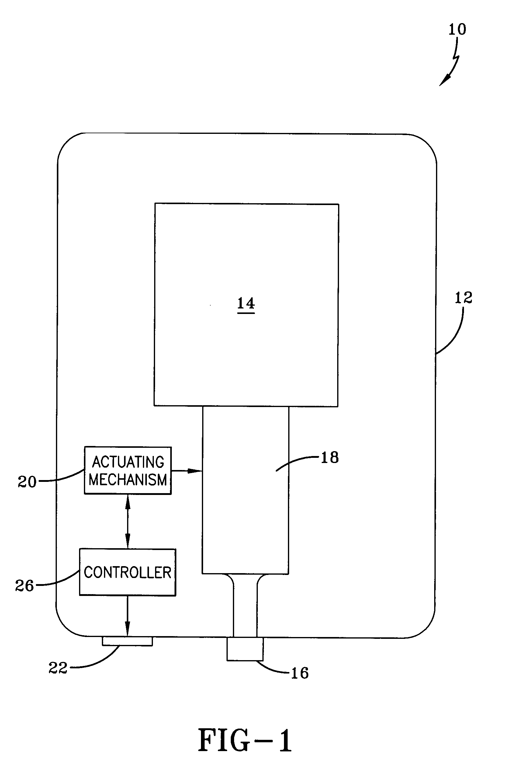
[0024]Referring now to the drawings and more particularly FIG. 1, it can be seen that a dispenser made in accordance with the invention is designated generally by the numeral 10. The dispenser 10 includes a dispenser housing structure of widely known dispensers, designated generally by the numeral 12. The dispenser housing 12 may be a wall or counter-mount unit, or can be a freestanding unit disposed on a counter top or the like. The dispenser described herein is used for dispensing fluids such as soaps and other liquids, but it will be appreciated that other products could be dispensed such as paper, tablets, or any flowable material. In any event, the dispenser housing 12 typically includes a cartridge of liquid product 14 positioned above and in communication with a dispensing nozzle 16, with an appropriate pump or other dispensing mechanism 18 interposed therebetween. As is well known by those skilled in the art, the dispensing mechanism 18 is configured to dispense a preset amo...


PUM


Abstract

A dispensing system is disclosed which utilizes a controller in conjunction with a photodetector in order to provide automatic dispensing to a user when an object enters a target area. A controller is programmed to pulse a light source that is mounted proximate the photodetector. The controller constantly monitors the voltage at the receiving signal of the photodetector, and evaluates the difference in voltage from the light pulsed on and off. The controller sums the differences, and constantly updates the differences over a designated period to create an average difference value. The average difference value is summed with a target offset value and compared to a momentary voltage difference. When the momentary difference exceeds the sum of the target offset value and average difference, the controller sends a signal to a dispense mechanism which dispenses a fluid or other product on the object.

Description

TECHNICAL FIELD[0001]The invention relates to fluid dispensers and methods for dispensing fluid. More particularly, the invention relates to electric “hands-free” fluid dispensers and methods for dispensing liquid fluid when an object enters a target field.BACKGROUND OF THE INVENTION[0002]Automatic dispensing devices that deliver liquids, towels, or other materials are known in the prior art. It is also well known that devices for automatically delivering fluid or the like onto the hands of a user, without requiring manual operation thereof or any physical contact therewith, are known in the prior art. It is well known in the art that such a dispenser may employ an electronic control circuit that monitors a voltage generated by a photo sensor to detect the presence of a user. Early hands-free devices employed a light-emitting diode (LED) in communication with a photodiode. When a user was within the target, the photodiode voltage changed and a signal was sent to supply power to a di...

Claims


Application Information

Patent Timeline
Patent Type & Authority Patents(United States)
IPC IPC(8): F16K51/00B67D7/08G01S7/486G01S17/04
CPCA47K5/1217G01S17/88G01S17/026G01S7/486G01S17/04A47K10/34B65H26/00
Inventor WEGELIN, JACKSON W.CURTIS, CHIP W.
Owner KANFER JOSEPH S
Why Eureka
Try Eureka