
Method and apparatus for removing coatings from a substrate using multiple sequential steps

a technology of coating and substrate, applied in the direction of grinding/polishing apparatus, grinding machine components, manufacturing tools, etc., can solve the problems of damage to the underlying base metal, ineffective, and inability to control the abrasive water jet in a way

Inactive Publication Date: 2011-03-01
OPTOMEC INC
View PDF17 Cites 23 Cited by
  • Summary
  • Abstract
  • Description
  • Claims
  • Application Information

AI Technical Summary

Benefits of technology

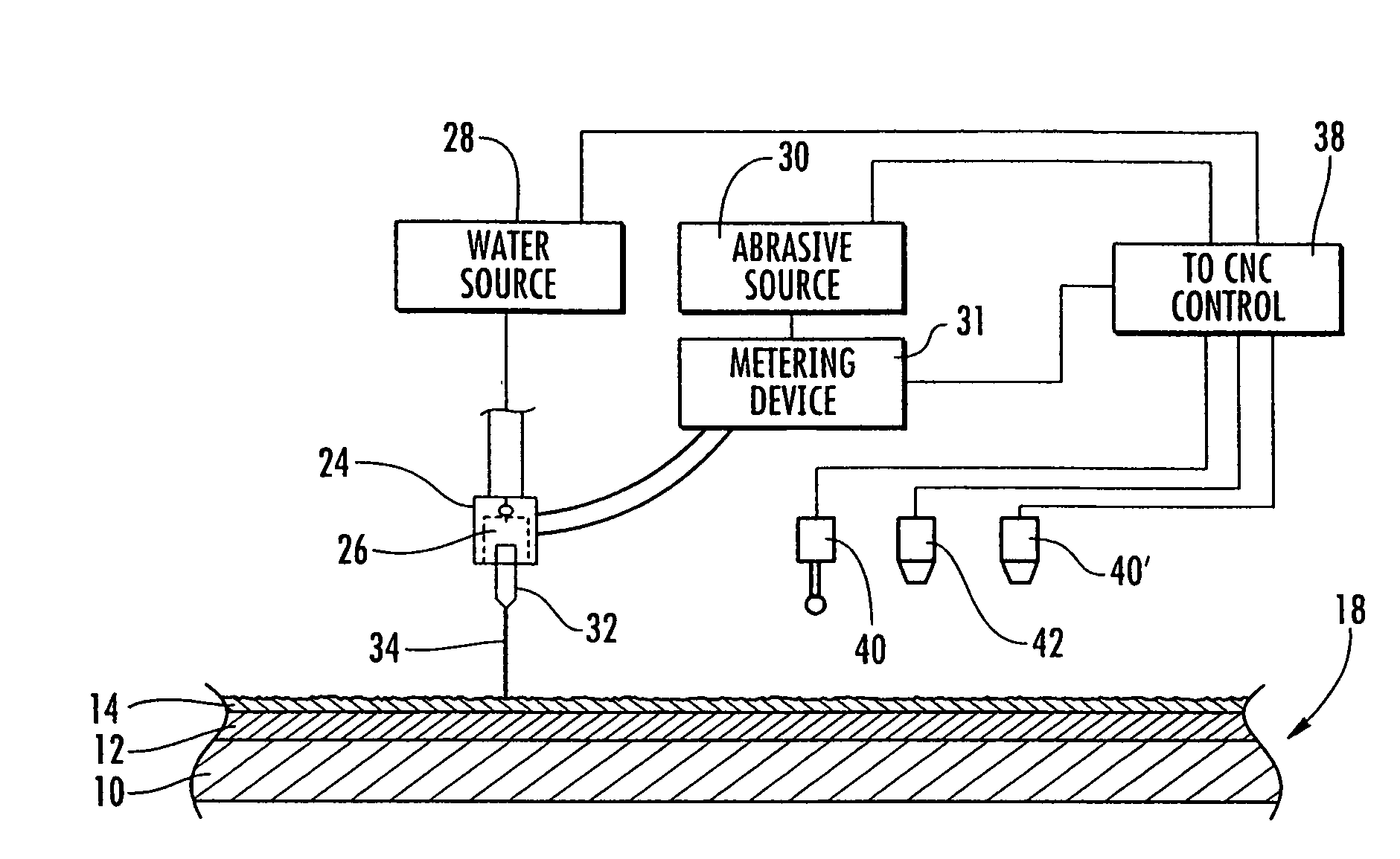
The system effectively removes coatings in a controlled manner, smoothing the surface and ensuring a pristine base metal for new coatings by varying the abrasive water jet's rate based on surface topography and detecting unique elements in the diffusion layer to stop material removal accurately.

Problems solved by technology

However, as set forth in greater detail in U.S. Pat. No. 6,905,396, which is incorporated herein by reference, all of these known manually applied removal methods have various drawbacks in that they are not particularly effective in removing the more difficult bond coat, and, in the case of acid or chemical stripping, environmental problems are encountered and there is a tendency to damage the underlying base metal as part of the removal process.
However, even though the relative movement of the abrasive water jet across the workpiece surface is controlled, the abrasive water jet itself generally removes substantially equal amounts of the coatings during each pass of the abrasive water jet, and the abrasive water jet is not controlled in a way that would properly compensate for variations in the thickness of the TBC caused by the use of the workpiece, such as a turbine blade.

Method used


Image

  • Method and apparatus for removing coatings from a substrate using multiple sequential steps
  • Method and apparatus for removing coatings from a substrate using multiple sequential steps
  • Method and apparatus for removing coatings from a substrate using multiple sequential steps

Examples


Embodiment Construction

[0021]In describing the invention below, the substrate will sometimes be identified as a turbine blade, which is a typical machine part having coatings that are removable using the method of the present invention, but it is to be understood that the present invention could also be used in removing coatings from a variety of other substrates and machine parts, such as vanes, shrouds, liners and transition pieces.

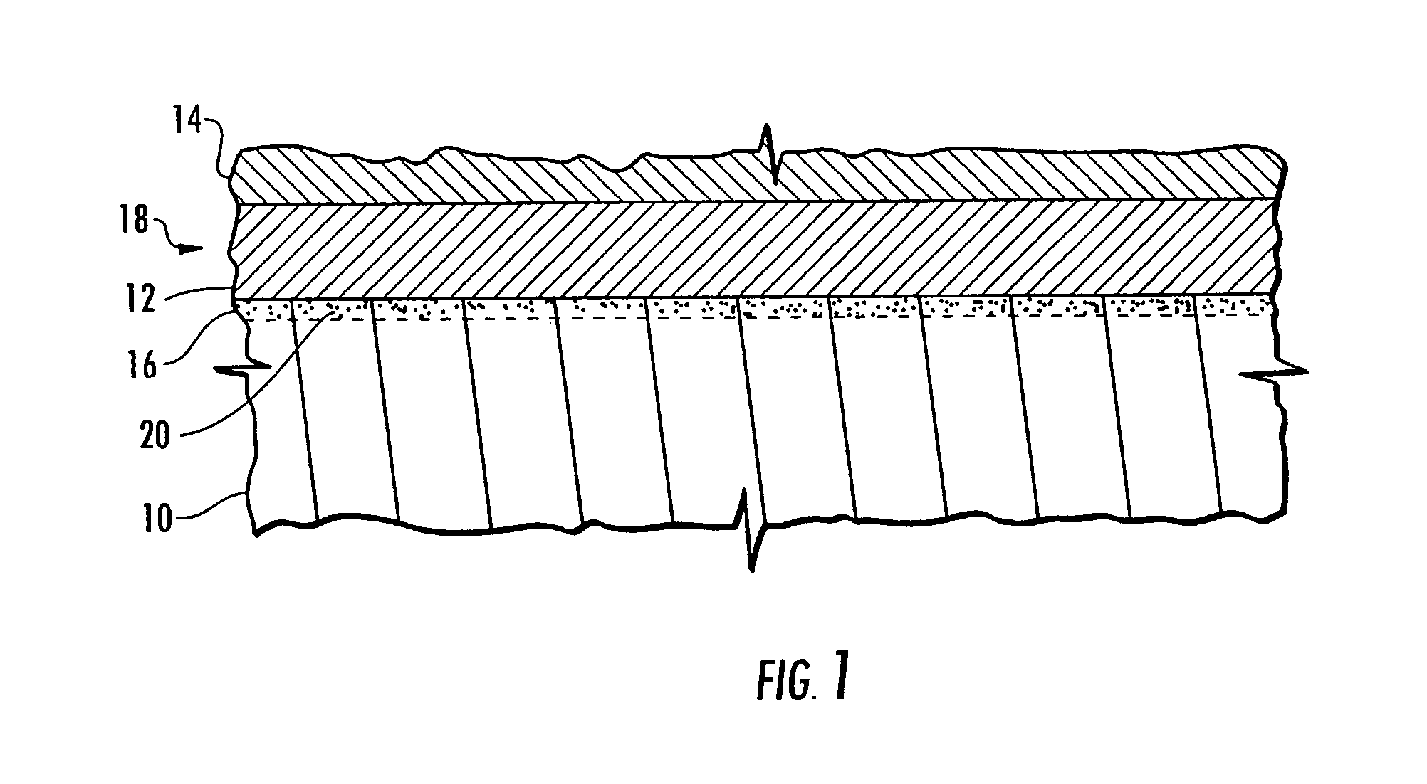
[0022]As seen in FIG. 1, the turbine blade 18 consists of a base metal 10 to which a bond coat 12 is diffusion bonded metallurgically to the base metal 10. The bond coat 12 is then overcoated with a ceramic material to form a TBC 14. It will be noted that the TBC 14 has a very irregular thickness and surface configuration which is a result of heat and other elements applied to the turbine blade in use, and this irregular surface configuration is exaggerated in FIG. 1 for purposes of illustration. Additionally, it will be noted that when the bond coat 12 is diffusion bonded to...


PUM

PropertyMeasurementUnit
thicknessaaaaaaaaaa
pressureaaaaaaaaaa
material removal rateaaaaaaaaaa

Abstract

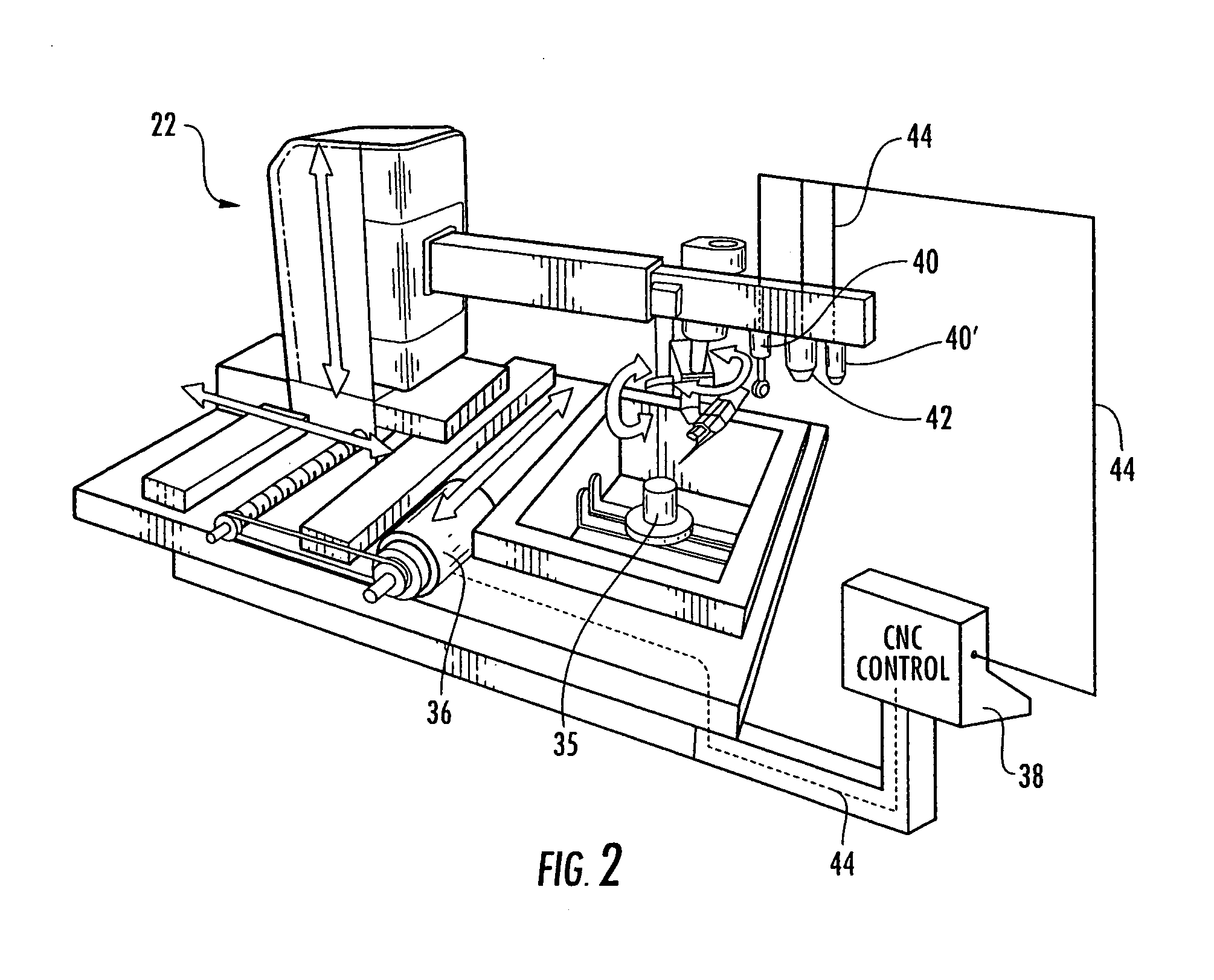
A method and apparatus for removing a coating having an irregular surface configuration that includes mapping the irregular surface configuration, and using the mapping determination in controlling the operation of an abrasive water jet to provide increased material removal rates at the higher points in the irregular surface and decreased material removal rates at the lower points, and thereby even out the surface configuration of the coating. The method and apparatus also includes using a detection device for detecting the presence or absence of an element that is unique to a layer of a coating, and using the detection determination in controlling the operation of the abrasive water jet to stop material removal of the coating when the detection device determines there is an absence of the unique element.

Description

CROSS-REFERENCE TO RELATED APPLICATIONS[0001]This application is a divisional of and thus is entitled to the benefit of, and claims priority to, U.S. patent application Ser. No. 11 / 999,667, filed Dec. 6, 2007, and entitled “Method And Apparatus For Removing Coatings From A Substrate Using Multiple Sequential Steps,” which claims priority of provisional U.S. Patent Application Ser. No. 60 / 874,571, filed on Dec. 13, 2006, and entitled “Method And Apparatus For Removing Coatings From A Substrate Using Multiple Sequential Steps,” the disclosures of which are incorporated herein by reference as if set forth fully herein.BACKGROUND OF THE PRESENT INVENTION[0002]The present invention relates generally to a method and apparatus for removing coatings from a workpiece or substrate, and more particularly to a method and apparatus for removing such coatings in a controlled sequence of steps.[0003]Some types of workpieces and parts require that one or more layers of coatings be applied to the wo...

Claims


Application Information

Patent Timeline
Patent Type & Authority Patents(United States)
IPC IPC(8): B24B49/00
CPCB24C1/086B24C9/00
Inventor MILLER, MITCHELL O.PEARSON, WILLIAM R.THOMPSON, WILLIAM R.
Owner OPTOMEC INC
Learn More