Adaptive howling canceller

a canceller and howling technology, applied in the field of adaptive cancellers, can solve the problems of significant severe impact on sound quality, etc., and achieve the effect of alleviating the degradation of sound quality and improving the estimation precision of filter coefficients

Inactive Publication Date: 2011-03-01
YAMAHA CORP
View PDF10 Cites 5 Cited by
  • Summary
  • Abstract
  • Description
  • Claims
  • Application Information

AI Technical Summary

Benefits of technology

[0014]The object of the present invention is to provide a novel adaptive howling canceller which allows the howling to be positively prevented from developing in a room with long reverberation time.

Problems solved by technology

In accordance with the prior art described above, when using an adaptive filter 7 which is shorter (has smaller number of taps) as compared with the transfer function H(z), there may arise a problem that the sound quality is severely affected.
However, since the adaptive filter 7 simulates only 256 taps of the head part with respect to the transfer function H(z) that has total 48,000 taps, the simulation of the transfer function H(z) is not sufficient so that the signal e(k) has a higher level and the sound quality is significantly affected.
However, since LMS algorithm updates the filter coefficient for each sample, the update interval is obviously short (the time to compute a new filter coefficient is short), while the amount of computation per unit time (will be abbreviated as “amount of computation” herein below) required for the update of filter coefficient increases in proportion to the number of taps.
Therefore, the sound quality is severely affected and the sound quality is inevitably decreased.
However, if the howling develops much quicker than the update period of filter coefficient, the update of filter coefficient is likely to delay when compared to the development of howling, some howling might be developed transitorily.

Method used


Image

  • Adaptive howling canceller
  • Adaptive howling canceller
  • Adaptive howling canceller

Examples


Embodiment Construction

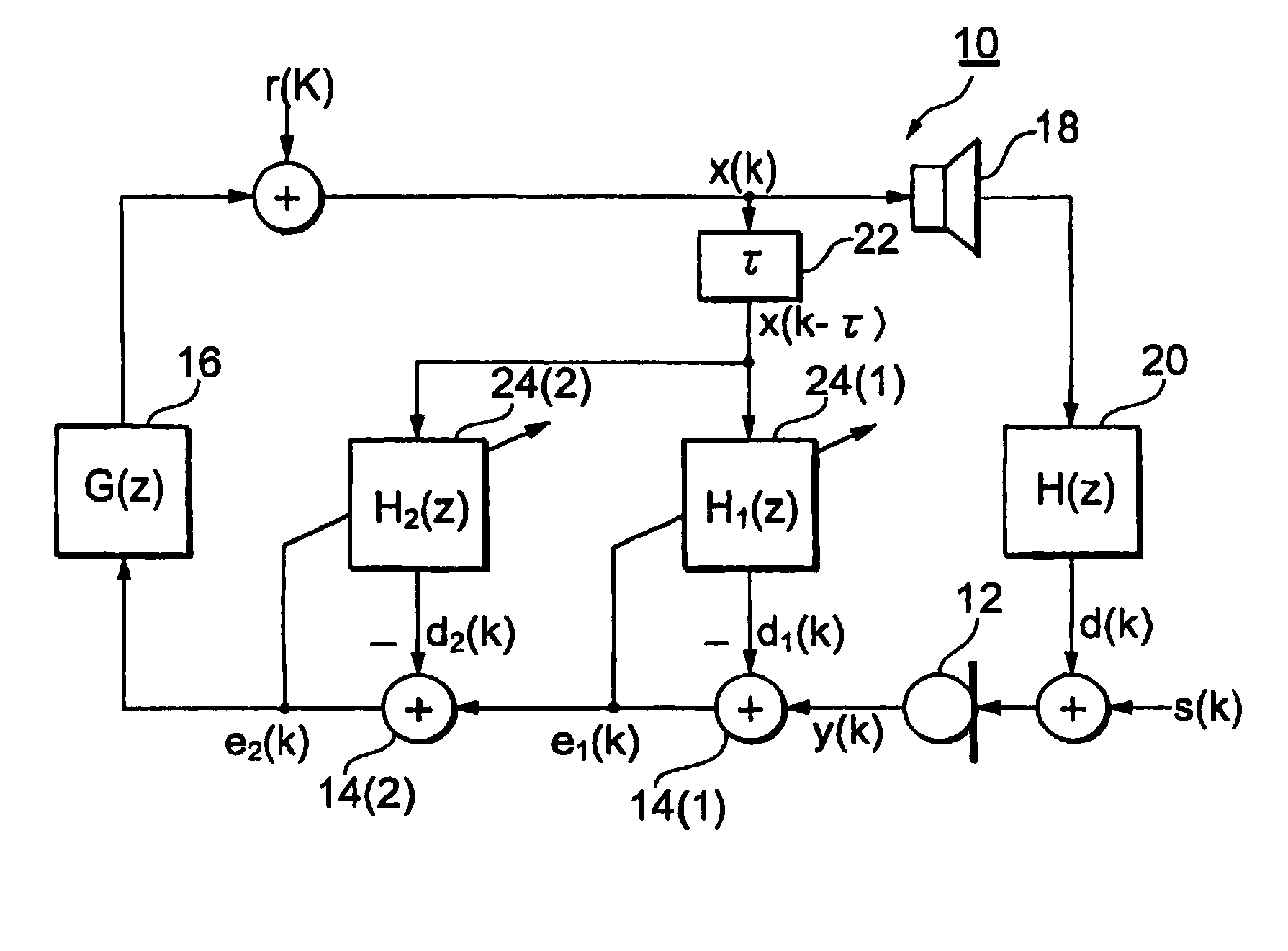
[0038]FIG. 1 shows a sound-reinforcement system incorporating the adaptive howling canceller in accordance with a first preferred embodiment of the present invention. In a given space such as an auditorium or a hall, a microphone 12 and a speaker 14 are placed. The audio signal input through the microphone 12 is transformed to signal y(k) in the digital form by an A / D conversion process. The signal y(k) is fed through adder units 14 (1), 14 (2) to an amplifier unit 16 for amplification. The amplifier unit 16 may or may not have a filter function (frequency component change function) in addition to amplification function. G(z) designates to a transfer function of the amplifier unit 16. Signal x(k) output from the amplifier unit 16 is D / A converted to a signal in the analog form, which signal is then transformed by the speaker 18 to the acoustic sound. Here r(k) indicates noise component, and the symbol of adder which receives r(k) indicates that some noise is penetrated.

[0039]An acou...


PUM


Abstract

An adaptive howling canceller has a plurality of adaptive filters. A delay adds a time delay of an acoustic feedback path to an electric signal fed from an amplifier of a sound-reinforcement system. Each adaptive filter filters the output signal of the delay with a filter coefficient, which is periodically updated at an update interval. The update interval of each adaptive filter is set to decrease successively from a first one to a last one of the adaptive filters. Adders are arranged in correspondence to the adaptive filters in series between a microphone and the amplifier. Each adder subtracts the output signal of the corresponding adaptive filter from an output signal fed from a preceding adder to thereby provide an output signal to a succeeding adder. The output signal from each adder is inputted into the corresponding adaptive filter. The audio signal from the microphone is inputted to the first adder, while the output signal from the last adder is inputted through the amplifier to the speaker and to the delay as the electric signal. The filter coefficient of each adaptive filter is updated so as to simulate a transfer function of the acoustic feedback path based on the output signals of the corresponding adder and the delay.

Description

BACKGROUND OF THE INVENTION[0001]1. Technical Field[0002]The present invention is directed to an adaptive howling canceller for use in preventing howling from developing in a sound-reinforcement system installed in auditoria, halls and the like.[0003]2. Related Art[0004]Hitherto, there are known adaptive howling cancellers for preventing howling from developing by using an adaptive filter (adaptive digital filter). Such a technology is disclosed for*example in non-patent document of Inazumi, Imai, and Konishi: “howling prevention in a sound-reinforcement system using the LMS algorithm”, Acoustical Society of Japan, proceedings pp. 417-418 (1991, 3).[0005]FIG. 12 shows a schematic circuit diagram of a sound-reinforcement system with the type of howling canceller equipped. A microphone 1 and a speaker 4 are placed in a given room. The audio signal input through the microphone 1 is transformed to a signal y(k) in a digital domain through an A / D (analog to digital) conversion process. T...

Claims


Application Information

Patent Timeline
Patent Type & Authority Patents(United States)
IPC IPC(8): H04R27/00H04B3/20H04M9/08
CPCH04R3/02G10K2210/506G10L2021/02082H04M9/082H04R25/453
Inventor OKUMURA, HIRAKUFUJITA, HIROAKI
Owner YAMAHA CORP
Why Eureka
Try Eureka