Digital microphone

a digital microphone and microphone body technology, applied in the field of digital microphones, can solve the problems of large area of amplifier die, inability to meet the needs of new high-sensitivity telecom microphones, and large physical size of filter elements, so as to achieve high input impedance, reduce the effect of reducing and reduce the size of the filter

Active Publication Date: 2011-03-01
ANALOG DEVICES INC
View PDF15 Cites 19 Cited by
  • Summary
  • Abstract
  • Description
  • Claims
  • Application Information

AI Technical Summary

Benefits of technology

[0026]Thus, it is an objective of the present invention to provide a preamplifier with the lowest possible input capacitance, lowest possible noise, largest output signal swing and at the same time exhibiting the lowest smallest possible chip area.
[0027]It is an objective of the present invention to provide a preamplifier having a large power supply rejection and low distortion.
[0028]It is an objective of the present invention to provide an amplifier which is able to handle slowly varying signals with relatively large amplitude at its input terminal while at the same time being able to amplify a low level signal with a higher frequency with low distortion.

Problems solved by technology

A so-called two stage preamplifier configuration, in which a simple buffer amplifier is followed by filter, has two disadvantages: as it has two stages, it is noisier and because there is no gain in the first stage the physical size of the filter has to be relatively large.
Thus such a solution, originally developed for hearing aid microphones, will be far from optimal for new high sensitive telecom microphones.
The area of the amplifier die would simply be too large and the device consequently too costly.
Therefore, since amplifier configurations known from hearing aids are generally not optimised for chip area to the same extent as telecom microphones, these configurations are not applicable for telecom applications.
Further, one should bear in mind that buffers or amplifiers applied in hearing aids are not configured to provide such high gain levels as are required for the low-sensitivity microphones used in telecommunication applications.
However, the capacitor microphone in combination with the input impedance of the amplifier will form a filter with only a very slowly decaying impulse response.
Further, the configuration is sensitive to overload caused by a largely uneven distribution of the signal spectrum generated by the microphone.
Although this configuration addresses important signal processing aspects, basic, but key implementation problems related to performance in terms of cost and noise are left unsolved.
Each contributes to increasing the noise level.
Additionally, the several stages occupy a large chip area which implies higher costs.
Further, the configuration is sensitive to overload caused by a largely uneven distribution of the signal spectrum generated by the microphone.
However, this configuration is not suitable since the gain of the amplifier is dependent on the microphone.
Further, noise of the preamplifier cannot be optimized independently of the microphone element.

Method used


Image

  • Digital microphone
  • Digital microphone
  • Digital microphone

Examples


Embodiment Construction

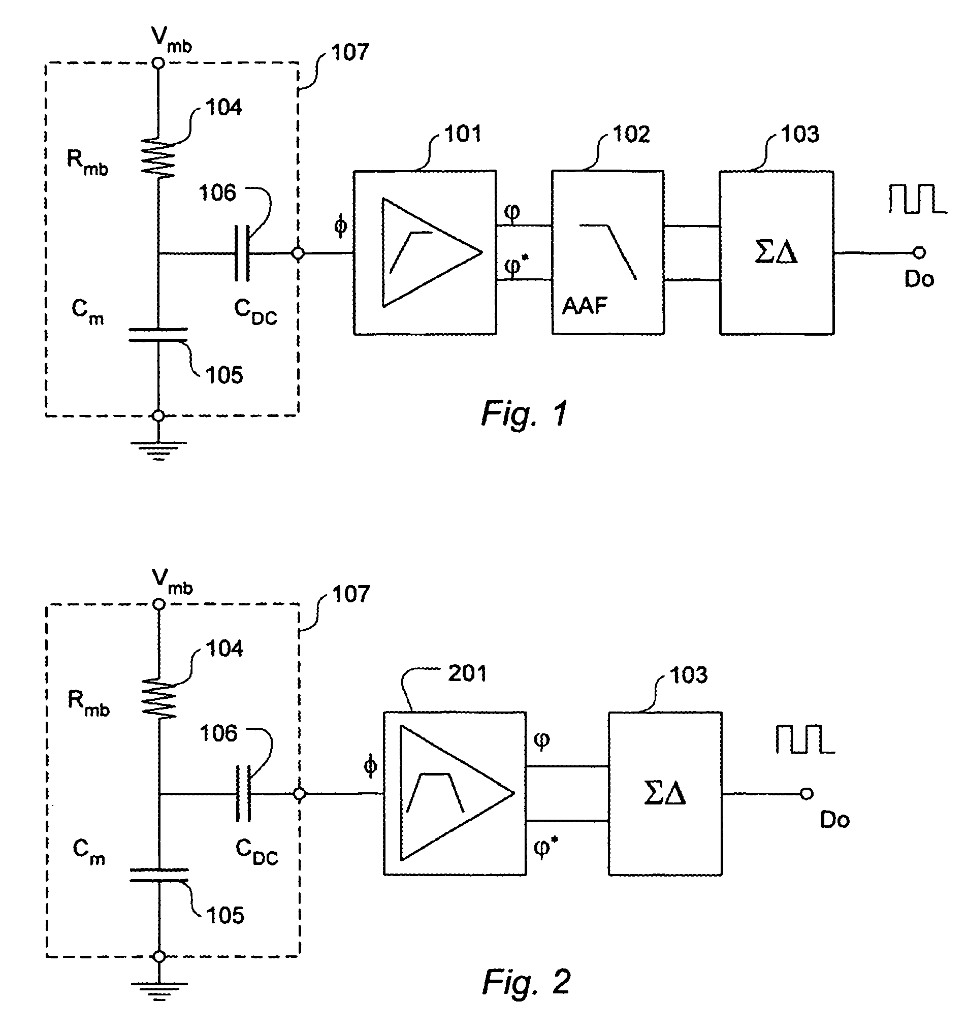
[0076]FIG. 1 shows a digital microphone comprising a microphone element, a preamplifier with a high-pass filter function, an anti-aliasing filter and an analogue-to-digital converter. The microphone element Cm, 105 comprises a first member in the form of a membrane or diaphragm that moves in response to a sound pressure acting on the membrane. The membrane moves relative to a second member typically a so-called back plate or simply a microphone casing which also serves for holding the movable membrane. One of the members, typically the second member is coupled to a ground reference whereas the other member, typically the membrane, is biased via a bias resistor Rmb, 104 that is coupled to a DC bias voltage Vmb. Thereby an electrical charge is provided on the membrane or movable member of the microphone element 105, Cm. Since the amount of charge is kept constant (for very low frequencies and up), an electrical microphone signal is provided by the membrane when it moves in response to...


PUM


Abstract

An integrated circuit, configured to process microphone signals, where the integrated circuit comprises: a preamplifier (306) with an amplifier section (301) which has a first input (φ) and a second input (φ*) and an output (φ), and with a feedback filter network (Z1; Z1, Z1*, Z2) coupled between the output (φ; φ, φ*) and the second input (φ′); where the first input (φ) to the amplifier section (301) has an input impedance which by means of the input impedance of the amplifier section is substantially isolated from the feedback network with respect to input impedance; and where the preamplifier has a frequency-gain transfer function which suppress low frequencies; and an analogue-to-digital converter coupled to receive an anti-aliasing filtered input signal and providing a digital output signal (Do).

Description

CROSS REFERENCE TO PRIOR APPLICATION[0001]The above-referenced application is a National Phase of International Patent Application of PCT / DK2005 / 000086 filed on Feb. 9, 2005, and claims the benefit of U.S. Provisional Application No. 60 / 542,305 filed Feb. 9, 2004 and Danish Patent Application No. PA 2004 01531, filed Oct. 6, 2004. The International Application was published on Aug. 18, 2005 as WO 2005 / 076466.[0002]The present invention relates to an integrated circuit comprising a microphone preamplifier and an analogue-to-digital converter to provide a digital output signal. Additionally, it relates to a digital microphone comprising a microphone element and an integrated circuit as set forth above.BACKGROUND[0003]A sound pressure detected by the microphone element will cause its membrane to move and consequently change the capacitance of the capacitor formed by its membrane and a so-called back plate of the microphone element. When the charge on the capacitor formed by these two m...

Claims


Application Information

Patent Timeline
Patent Type & Authority Patents(United States)
IPC IPC(8): H04R3/00H03M3/00H03F1/32H03F1/34H03F3/181H03F3/187H03F3/45H04R1/04H04R19/01H04R19/04
CPCH03F1/3211H03F1/34H03F3/181H03F3/187H03F3/45968H04R1/04H04R3/00H03F2200/03H03F2200/331H03F2203/45138H03F2203/45418H03F2203/45424H03F2203/45544H03F2203/45594H03F2203/45596H04R19/016H04R19/04
Inventor FURST, CLAUS ERDMANNTHOMSEN, HENRIKMUCHA, IGOR
Owner ANALOG DEVICES INC
Why Eureka
Try Eureka