Worm-rack type transmission device

a transmission device and worm-rack technology, applied in the direction of lifting devices, friction gearings, gearings, etc., can solve the problems of unsuitable for extended distance travel, unsuitable for scroll-shaped teeth, machine tools in the mechanical industry, etc., to achieve relevant power transmission and strengthen the engagement

Inactive Publication Date: 2011-03-08
KAMOSEIKO
View PDF12 Cites 6 Cited by
  • Summary
  • Abstract
  • Description
  • Claims
  • Application Information

AI Technical Summary

Benefits of technology

[0019]This enables to strengthening a transmission power to insure a high transmission efficiency with a least friction loss so as to effectuate a linear drive for an extended distance travel with a high precision.
[0022]This strengthens the engagement of the toothed streak against the curved side portion to more effectuate the advantages as mentioned in claim 1.
[0024]With the worm wheel inclined against the linear rack, it is possible to secure an extra space between the worm wheel and the linear rack. This leads to connecting the motor to the rear end of the worm wheel in alignment with the worm wheel, so as to structurally simplify the gear train (power transmission mechanism).
[0026]The carriage lift is used to carry goods and baggage, or used to send an operator to work at high elevation. With the power transmission mechanism simplified as mentioned in claim 3, it is possible to make the carriage lift compact and lightweight with the convenient self-locking mechanism attained.
[0028]With the rack teeth curved in the sigmoidal fashion, it is possible to strengthen the engagement between the curved side surface and the toothed streak so as to insure a more relevant power transmission.

Problems solved by technology

However, it is impossible to travel the rack pieces 54 beyond the central portion G to limit an amount of their travel which the rack pieces 54 can move, so as to make the scroll chuck device 52 unsuitable for an extended distance travel.
This lengthens a sliding distance of the scroll-shaped tooth 23 against the rack tooth 25, thus necessitating a strengthened drive power with no small friction loss accompanied, making it unsuitable to apply the scroll-shaped tooth 23 to the machine tools in the mechanical industry.
In general, in the worm wheel type transmission device with the worm wheel incorporated into a helical gear, the device has been extensively used because of its increased power transmission and self-locking property with a high precision albeit unsuitable for the usage of the extended distance travel.
In the pinion-rack mechanism, although it is suitable for the usage of the extended distance travel, it has no self-locking property and lacks an increased power transmission because of the limited number of teeth in which the pinion meshes with the rack.

Method used


Image

  • Worm-rack type transmission device
  • Worm-rack type transmission device
  • Worm-rack type transmission device

Examples


first embodiment

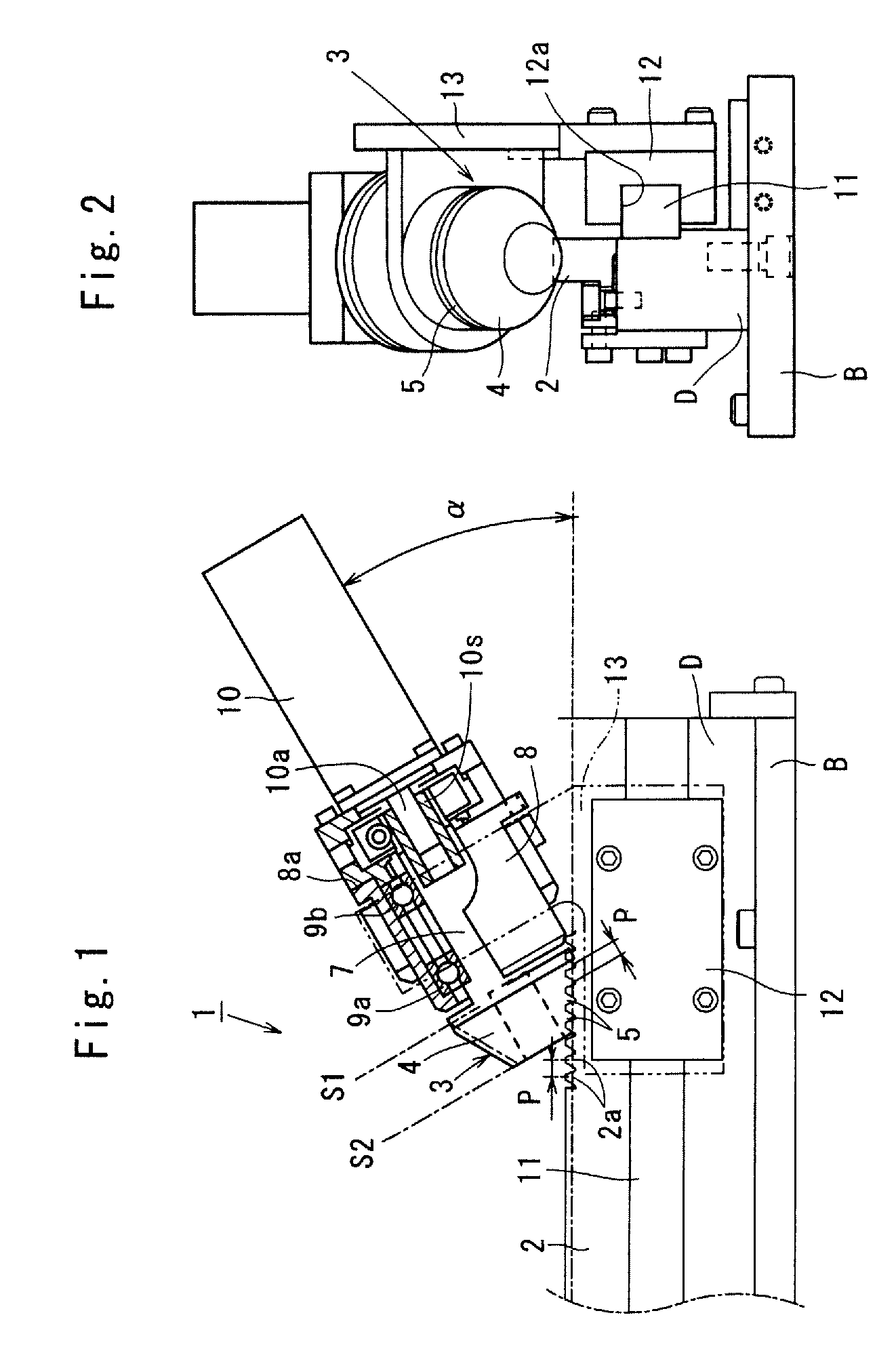
[0039]Referring to FIGS. 1 through 4 which show a worm-rack type transmission device 1 according to the invention, the worm-rack type transmission device 1 is used to a robot arm of a large-scaled machine tool installed in a floor of a machining factory.

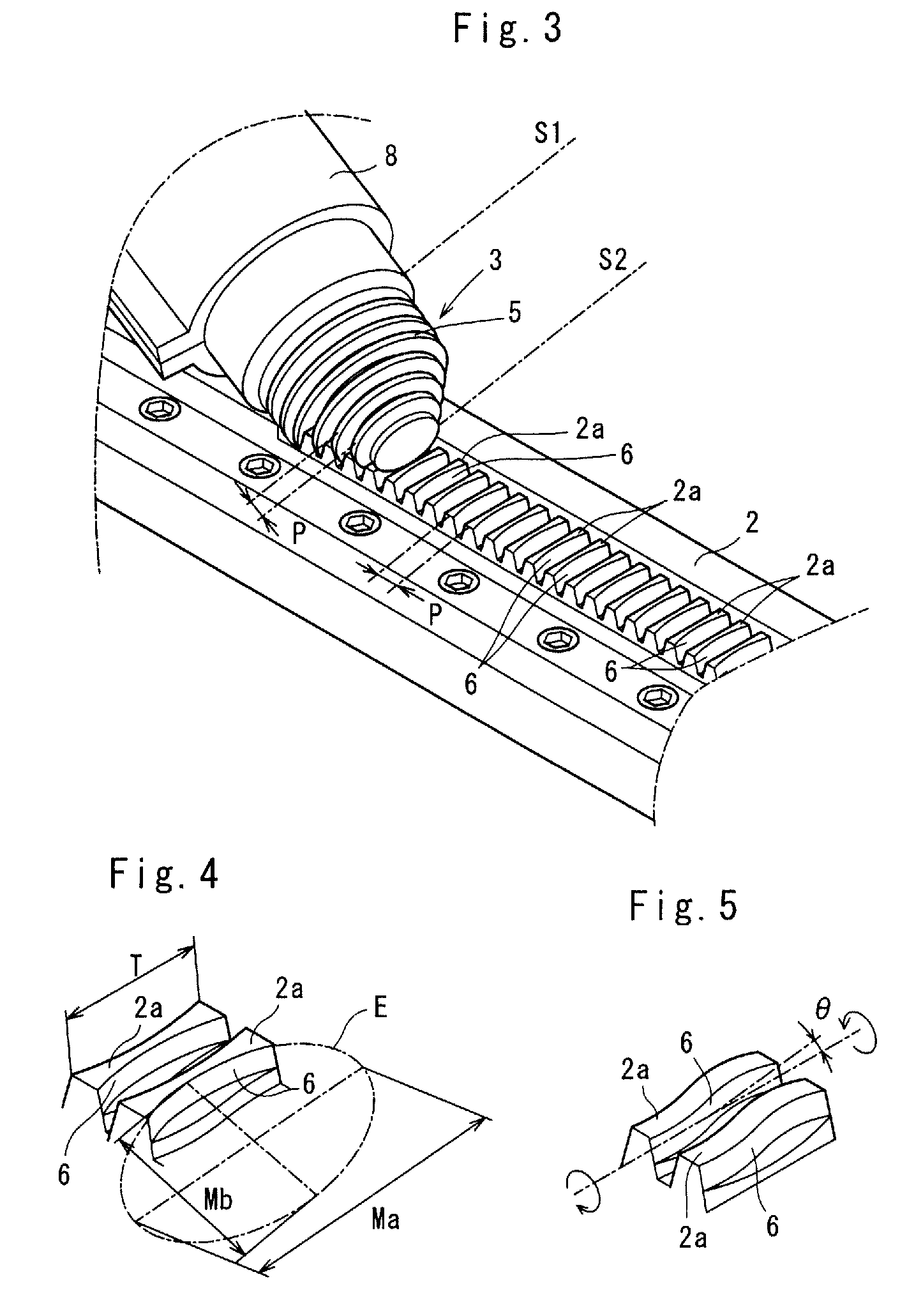
[0040]In the worm-rack type transmission device 1, a linear rack 2 is made of a metallic material (e.g., iron or mild steel) substantially rectangular in cross section, and placed on a metallic beam D installed on a base plate B as shown in FIGS. 1, 2. The linear rack 2 is adapted to slide along a lengthwise direction of the metallic beam D, and having a number of rack teeth 2a at predetermined pitch intervals P. As a tooth profile, the rack teeth 2a are substantially trapezoidal in cross section.

[0041]A worm wheel 3 has a frustocone-shaped body 4 which is made of the metallic material (e.g., iron or mild steel). An outer surface of the frustocone-shaped body 4 integrally has a series of toothed streak 5 helically running therealong ...

second embodiment

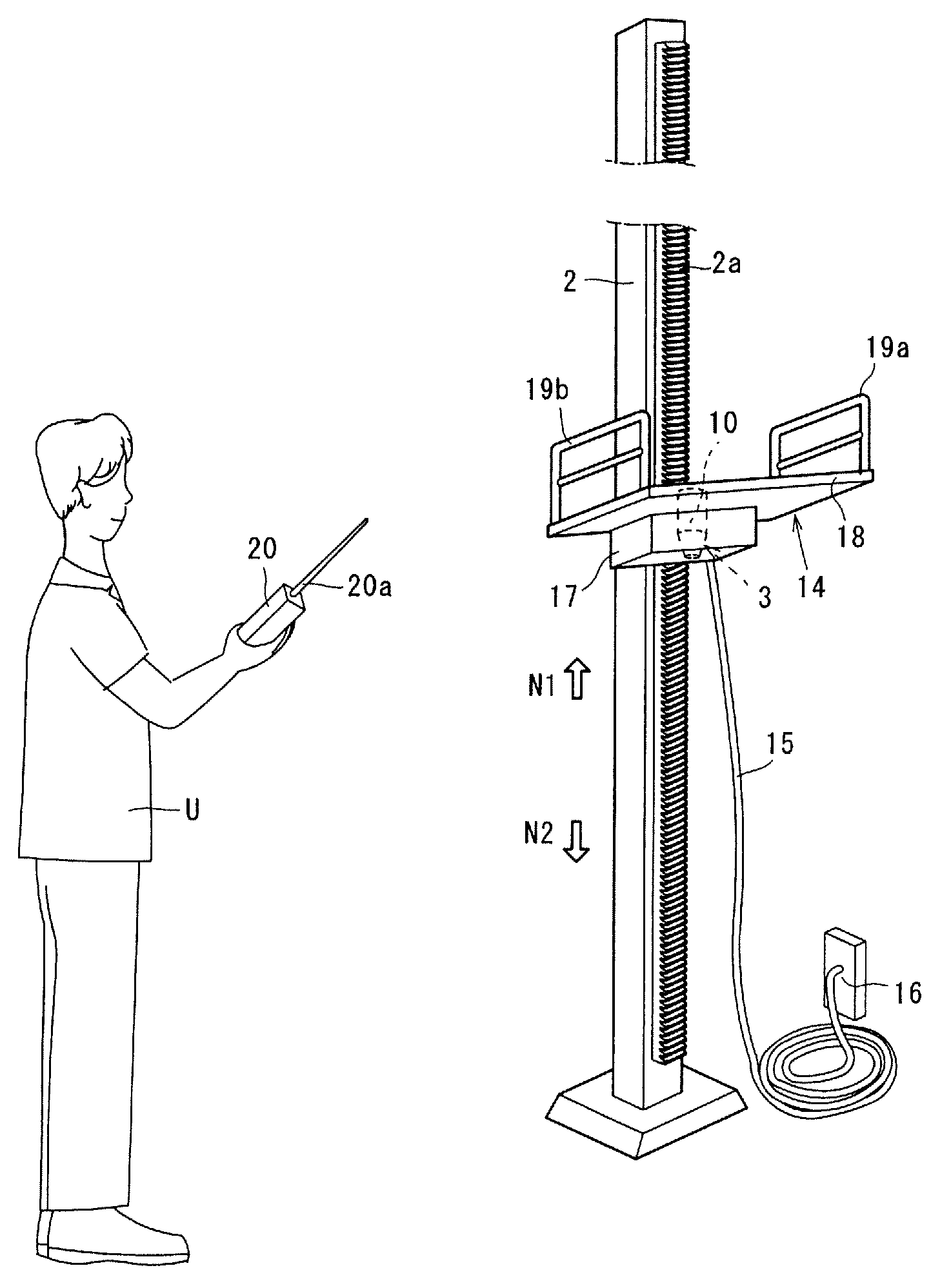
[0058]FIG. 6 shows the invention in which the worm-rack type transmission device 1 is incorporated in carriage lift 14. The linear rack 2 is vertically set on a stand with worm wheel 3 placed within the carriage lift 14. The carriage lift 14 is used to carry goods and baggage, or used to send an operator (not shown) to work at a high elevation.

[0059]The carriage lift 14 has an accommodation box 17, a horizontal pallet 18 placed on the box 17 and hand rails 19a, 19ba vertically fixed to a right and left side of the pallet 18. Inside the box 17, the worm wheel 3, the housing 8 and the motor 10 are firmly placed. The motor 10 is connected to a power source outlet 16 by way of a conductive cord 15. In FIG. 6, the guide bar 11, the slider plate 12, the guide plate 13 are omitted for the purpose of convenience.

[0060]When a user U actuates a remote control device 20 with the goods, baggage or the operator laid on the pallet 18, the motor 10 is energized through an antenna 20a to rotate the...


PUM


Abstract

In a worm-rack type transmission device (1), a curved side portion (6) is provided on rack teeth (2a) of a linear rack (2) in a manner to form a part of an ellipsoidal surface (E) and twisted by a changing rate (θ) of a torsional manner a toothed streak (5) of a worm wheel (3). The worm wheel (3) brings the toothed streak (5) into engagement with the curved side portion (6) in a line-to-line contact, enabling to a self-locking property and strengthening a transmission power to insure a high transmission efficiency with a least friction loss so as effectuate a linear drive for an extended distance travel with a high precision.

Description

BACKGROUND OF THE INVENTION[0001]1. Field of the Invention[0002]The invention relates to a worm-rack type transmission device which has a worm wheel and a linear rack to transmit the former rotational movement to the latter to convert it as a linear movement, and particularly to a worm-rack type transmission device in which the worm wheel is formed into a frustocone-shaped configuration.[0003]2. Description of Prior Art[0004]In a worm-rack type transmission device well-suited to transfer a large-scaled machine tool as shown in FIG. 7, a worm wheel 50 is placed on a half-nut type rack 51 with a worm tooth 50a engaged against a rack tooth 51a of a linear rack 51. The worm wheel 50 directs its shaft 50b in parallel with an axial direction of the linear rack 51.[0005]Upon rotating the worm wheel 50 by way of an electric motor (not shown), the linear rack 51 moves in its lengthwise direction N to actuate a robot arm (not shown) of the machine tool so as to transfer component parts of mac...

Claims


Application Information

Patent Timeline
Patent Type & Authority Patents(United States)
IPC IPC(8): B66F3/08
CPCB66F3/18F16H19/04B66F11/04Y10T74/18792
Inventor IMASE, KENJI
Owner KAMOSEIKO
Why Eureka
Try Eureka