
Apparatus and method for producing color filters by discharging material

a technology of color filters and discharge tubes, which is applied in the direction of inking apparatus, electromagnetic radiation sensing, instruments, etc., can solve the problems of increasing the main scanning time for ink discharge, the need to further increase the main scanning time, and the difficulty of forming an ink jet head, so as to shorten the time required for producing an el device, and shorten the scanning time

Inactive Publication Date: 2011-03-08
KATEEVA
View PDF49 Cites 15 Cited by
  • Summary
  • Abstract
  • Description
  • Claims
  • Application Information

AI Technical Summary

Benefits of technology

[0015]A possible method for solving the problem is to incline the supporting member 307 at an angle θ with the sub-scanning direction Y, coinciding the nozzle pitch of the heads 306 with the element pitch on the mother board 301, as shown in FIG. 23(b). However, in this case, a deviation with a dimension Z in the main scanning direction X occurs in the nozzle row formed by the heads 306 arranged in a row, thereby causing the problem of increasing the main scanning time for ink discharge by a time corresponding to the deviation. Particularly, in the use of such a six-linked structure head unit as shown in FIG. 23(b), the deviation has a long dimension because of the long nozzle row, thereby causing the problem of the need to further increase the main scanning time.
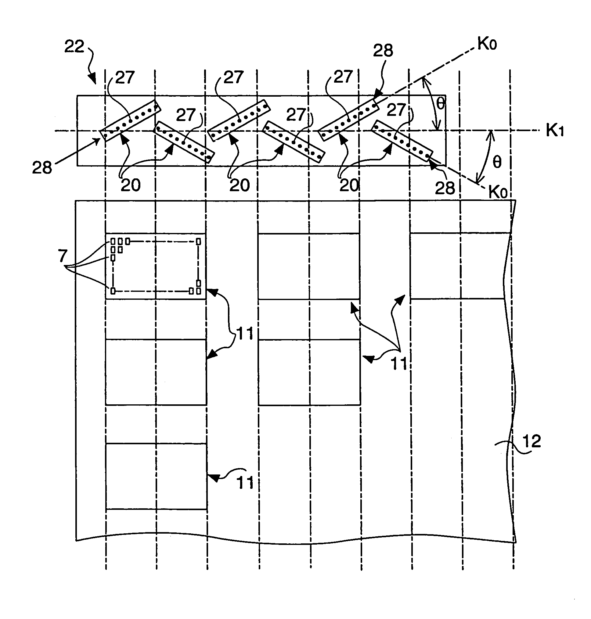
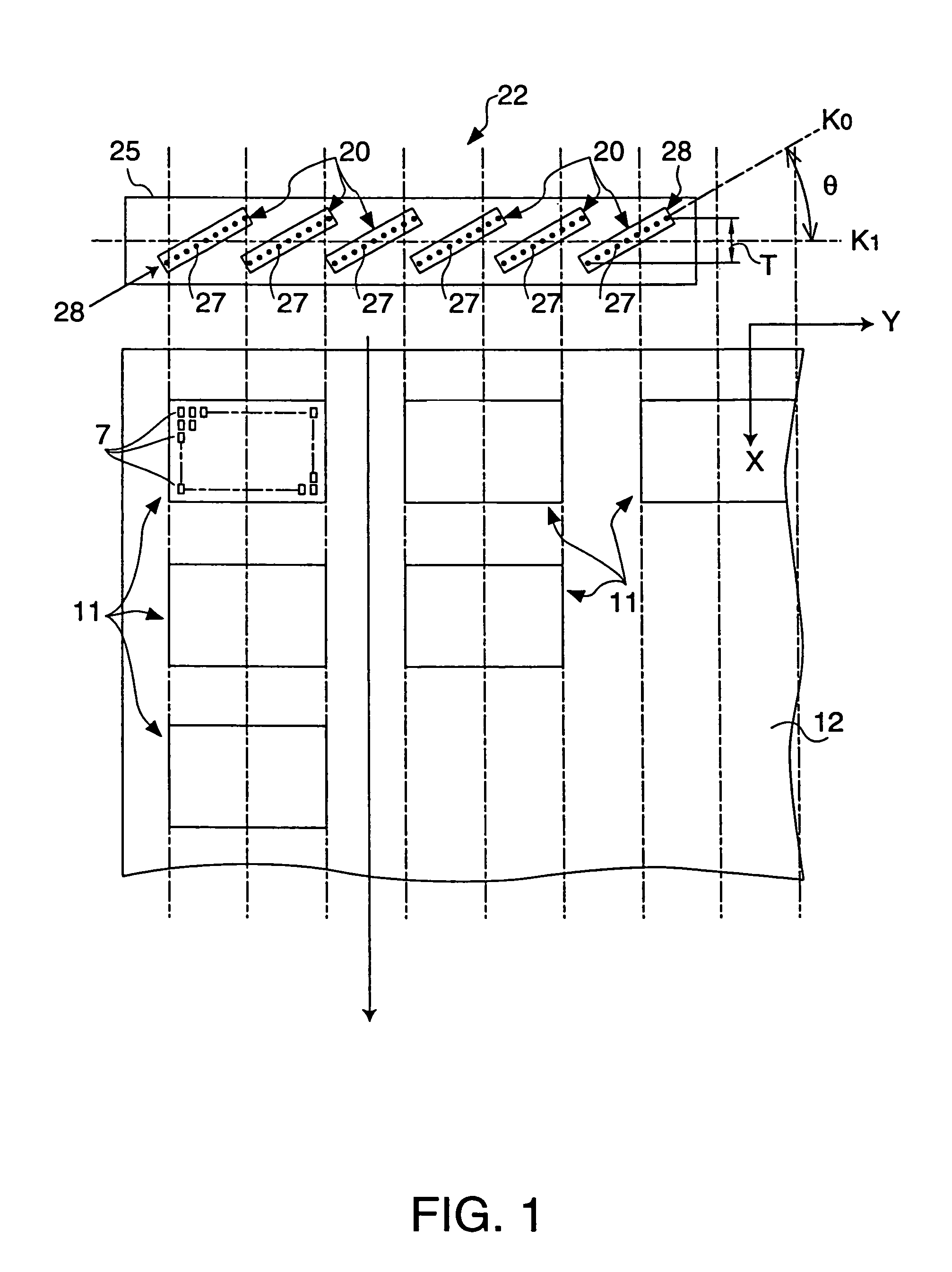
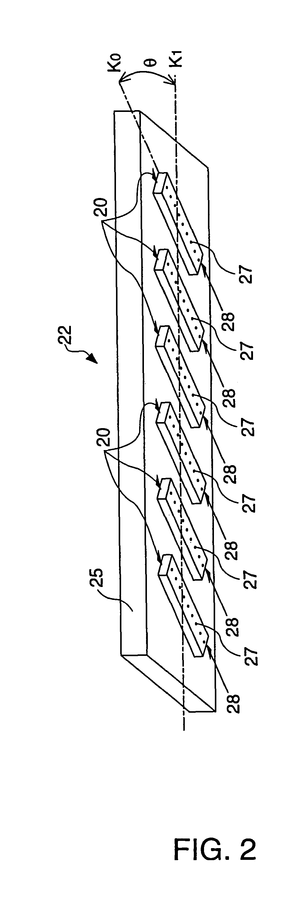
[0059]Since scanning is performed with the each of the heads in an inclined state, the nozzle pitch of the nozzles belonging to each of the heads can be coincided with the pixel pitch of the picture element pixels formed on the substrate. Furthermore, since each of the heads is inclined, and not a row of the plurality of heads, the distance between the nozzle closest to the substrate and the nozzle far from the substrate is shorter than the case in which the head row is inclined, thereby shortening the scanning time of the substrate with the plurality of nozzle rows. Therefore, the time required for producing an EL device can be shortened.

Problems solved by technology

However, it is very difficult to form an ink jet head so that the nozzle pitch is the same as the element pitch.
However, in this case, a deviation with a dimension Z in the main scanning direction X occurs in the nozzle row formed by the heads 306 arranged in a row, thereby causing the problem of increasing the main scanning time for ink discharge by a time corresponding to the deviation.
Particularly, in the use of such a six-linked structure head unit as shown in FIG. 23(b), the deviation has a long dimension because of the long nozzle row, thereby causing the problem of the need to further increase the main scanning time.

Method used


Image

  • Apparatus and method for producing color filters by discharging material
  • Apparatus and method for producing color filters by discharging material
  • Apparatus and method for producing color filters by discharging material

Examples


Embodiment Construction

[0085]A method and apparatus for producing a color filter according to an embodiment of the present invention will be described below. Before the production method and apparatus are described, a color filter produced by the production method is described. FIG. 6(a) schematically shows the planar structure of a color filter according to an embodiment. FIG. 7(d) shows a sectional structure taken along line VII-VII in FIG. 6(a).

[0086]The color filter 1 of this embodiment includes a plurality of filter elements 3 which are formed in a dot pattern, which is in this embodiment a dot matrix, on a surface of a rectangular substrate 2 made of glass, plastic, or the like, and a protecting film 4 laminated on the filter elements 3 as shown in FIG. 7(d). FIG. 6(a) is a plan view of the color filter 1 with the protecting film 4 being removed. Namely, in this embodiment, a color pattern formed by ink jet is illustrated by the filter elements 3.

[0087]The filter elements 3 can be formed by filling ...


PUM

PropertyMeasurementUnit
sizeaaaaaaaaaa
sizeaaaaaaaaaa
distanceaaaaaaaaaa

Abstract

The present invention provides a system which shortens the scanning time with an ink jet head for forming a pattern of filter elements of a color filter, picture element pixels of an electroluminescence (EL) device, or the like. An apparatus for producing a color filter can include a plurality of filter elements arranged on a substrate. The apparatus can further include a plurality of heads each having a nozzle row having a plurality of nozzles arranged, an ink supply device for supplying a filter element material to the heads, a carriage supporting the heads arranged thereon, a main scanning driving device for moving the carriage by main scanning in the X direction, and a sub-scanning driving device for moving the carriage by sub-scanning in the Y direction. The carriage supports the plurality of heads each of which is inclined at an in-plane inclination angle θ.

Description

[0001]This is a Division of application Ser. No. 10 / 043,244 filed Jan. 14, 2002. The entire disclosure of the prior application is incorporated by reference herein in its entirety.BACKGROUND OF THE INVENTION[0002]1. Field of Invention[0003]The present invention relates to an apparatus and method for discharging a material onto an object. Particularly, the present invention relates to an apparatus and method for producing a color filter used for optical devices such as a liquid crystal device, and the like. The present invention also relates to an apparatus and method for manufacturing a liquid crystal device having a color filter. The present invention further relates to an apparatus and method for manufacturing an electroluminescence (EL) device for displaying by using an EL luminescent layer. The present invention further relates to an electronic apparatus manufactured by any one of the above-described methods.[0004]2. Description of Related Art[0005]Recently, display devices, suc...

Claims


Application Information

Patent Timeline
Patent Type & Authority Patents(United States)
IPC IPC(8): G06K7/10B41J2/01B41J2/155B41J2/21G02B5/20G02F1/13G02F1/1335H01L27/32H01L51/00H01L51/40
CPCB41J2/155B41J2/2103G02B5/201B41J2202/09B41J2202/20G02F1/133516H01L27/32H01L51/0005H10K71/135G02F1/13H10K59/00
Inventor KATAGAMI, SATORUARUGA, HISASHIKIGUCHI, HIROSHIITO, TATSUYAKAWASE, TOMOMISHIMIZU, MASAHARU
Owner KATEEVA
Learn More