Method of thin film electrospray deposition

Active Publication Date: 2011-03-15
UNIV OF SOUTH FLORIDA
View PDF5 Cites 9 Cited by
  • Summary
  • Abstract
  • Description
  • Claims
  • Application Information

AI Technical Summary

Benefits of technology

[0006]Methods currently available for the fabrication of smooth continuous thin films by electrospray deposition have the problem of long deposition times. The present invention addresses this pro

Problems solved by technology

This results in much shorter depositio

Method used


Image

  • Method of thin film electrospray deposition
  • Method of thin film electrospray deposition
  • Method of thin film electrospray deposition

Examples


Embodiment Construction

[0030]In the following detailed description of the preferred embodiments, reference is made to the accompanying drawings, which form a part hereof, and within which are shown by way of illustration specific embodiments by which the invention may be practiced. It is to be understood that other embodiments may be utilized and structural changes may be made without departing from the scope of the invention.

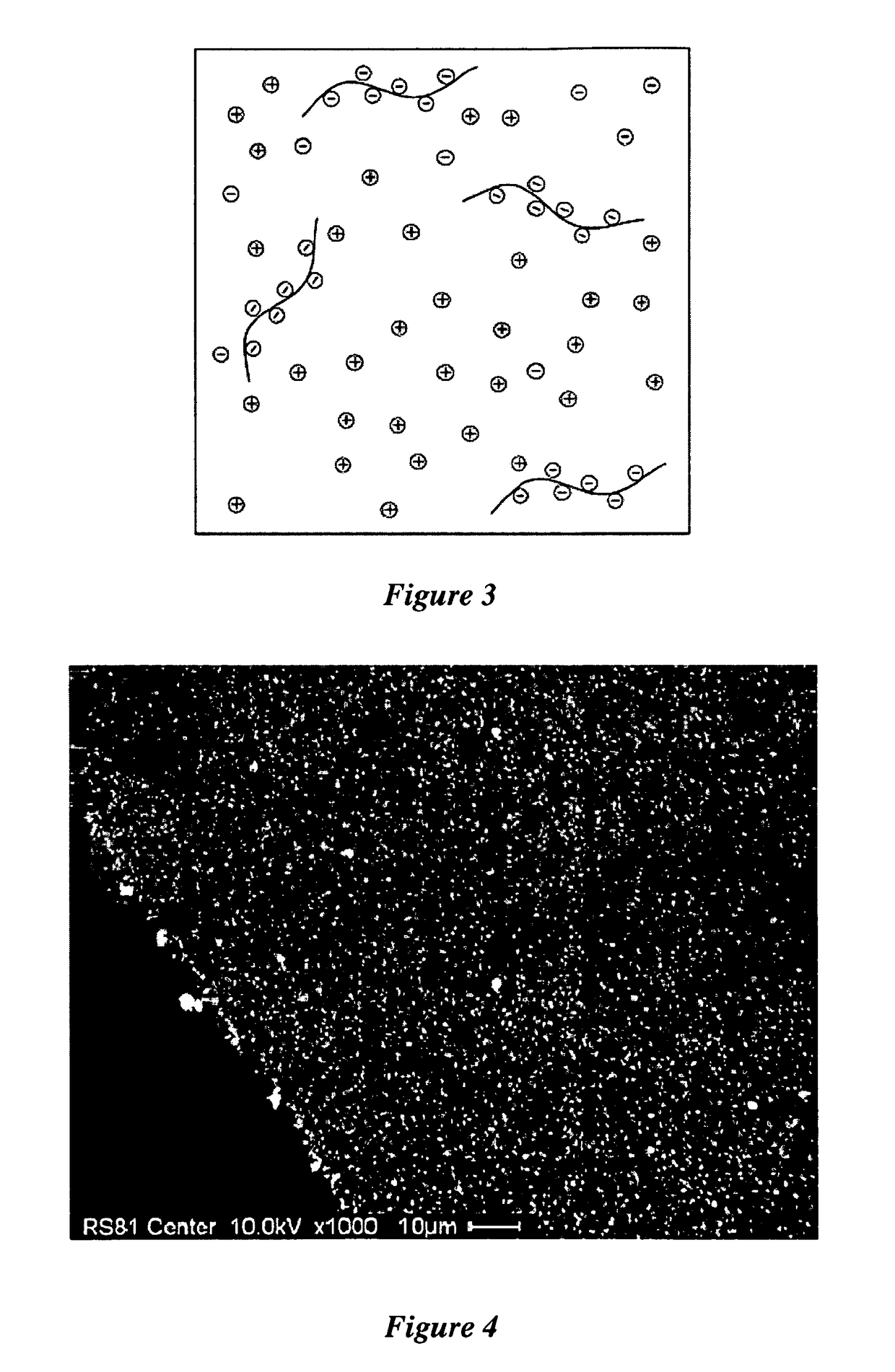
[0031]The present invention solves the problem of low-concentration / rough-coating application by introducing ionic substances (salts, acids, bases) to the solution to be sprayed.

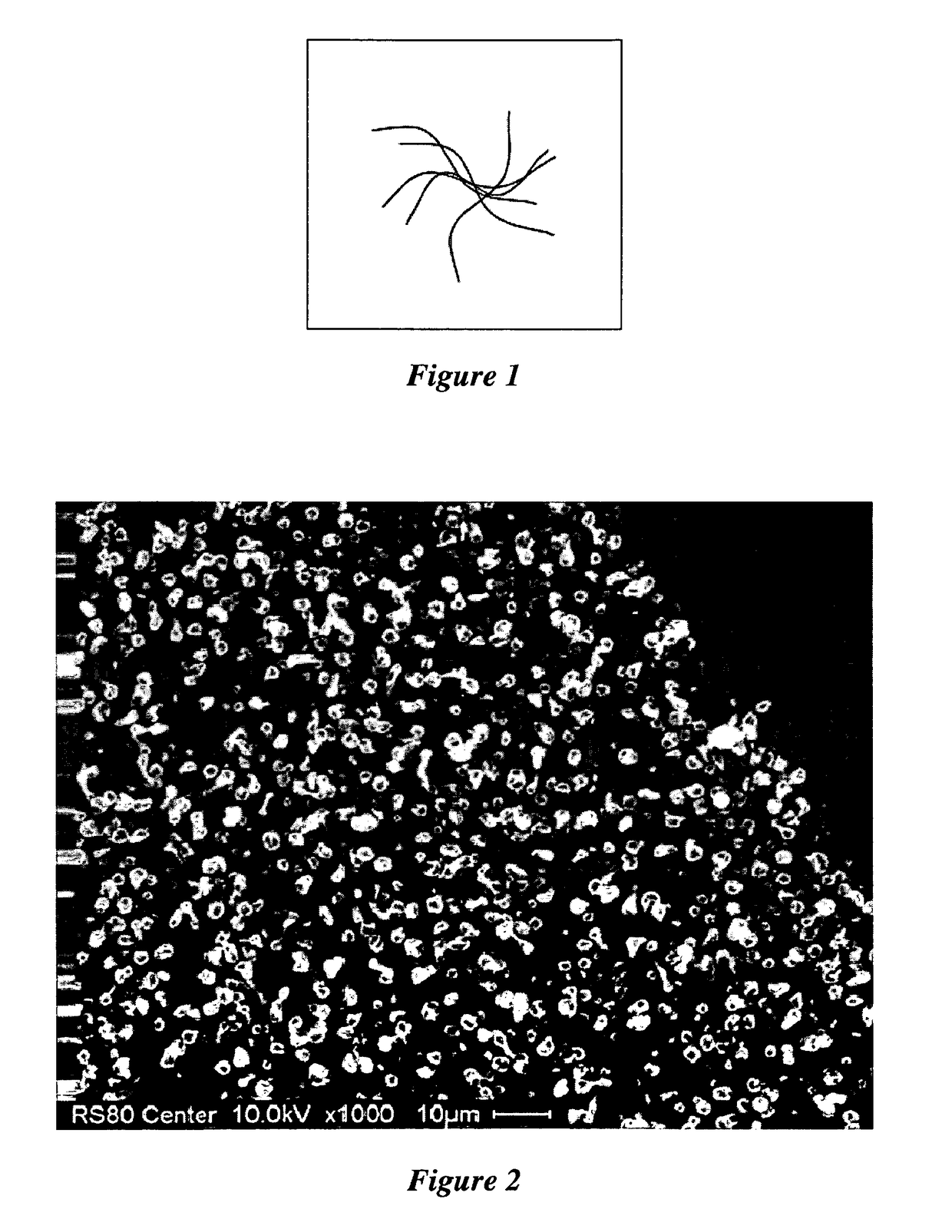
[0032]An illustration of pure polymer solution is shown in FIG. 1. When sprayed, droplets of the solution form. As the droplets fly towards the substrate, their size shrinks, i.e. the concentration of the polymers increases. At a certain point, due to Van der Waals attraction or a similar mechanism, the polymers are attracted to each other because there is no longer enough solvent to keep them separate (i.e. ...


PUM


Abstract

A method of forming a smooth thin film on a substrate within a short deposition time, the method comprising introducing ionic substances (salts, acids, bases) to a polymeric solution to be sprayed. These ions attach to the polymer strands in solution, increasing their charge to mass ratio. This results in mutual repulsion of the strands during the spray process and produces a smooth film, even at relatively high polymeric solution concentrations. A side effect of this process is the introduction of impurities (the added ions) to the polymer thin film. The proper choice of ionic compound allows a dissolution step to be used to “clean” the polymer film after deposition, using the solubility characteristics of the thin film versus the ionic compound.

Description

CROSS REFERENCE TO RELATED APPLICATIONS[0001]This application claims priority to currently pending U.S. Provisional Patent Application No. 61 / 021,743, filed Jan. 17, 2008.STATEMENT OF GOVERNMENT INTEREST[0002]This invention was made with Government support under Grant NSF DMR 0510000, awarded by the National Science Foundation, Division of Materials Research. The government has certain rights in the invention.FIELD OF THE INVENTION[0003]This invention relates to depositing films from highly concentrated solutions. More specifically, the invention is a method for electrospraying highly concentrated solutions and obtaining a substantially two-dimensional thin film.BACKGROUND[0004]Electrospray is a method of applying thin film coatings in industrial applications. As the coating solution passes through a nozzle, the solution is subject to an electrical charge. The charged solution repels itself and, upon exiting the nozzle, disperses into small, highly charged droplets. While aerosolize...

Claims


Application Information

Patent Timeline
IPC IPC(8): B05D1/04
CPCB05D1/04
Inventor SCHLAF, RUDIGER
Owner UNIV OF SOUTH FLORIDA
Why Eureka
Try Eureka