
Power production control system and method

a power production control and control system technology, applied in the direction of electric generator control, process and machine control, machines/engines, etc., can solve the problems of increasing regulation costs, requiring an increase in the already existing energy demand management and load shedding, and substantial challenges to incorporating large amounts of wind power

Active Publication Date: 2011-03-15
GENERAL ELECTRIC CO
View PDF3 Cites 22 Cited by
  • Summary
  • Abstract
  • Description
  • Claims
  • Application Information

AI Technical Summary

Benefits of technology

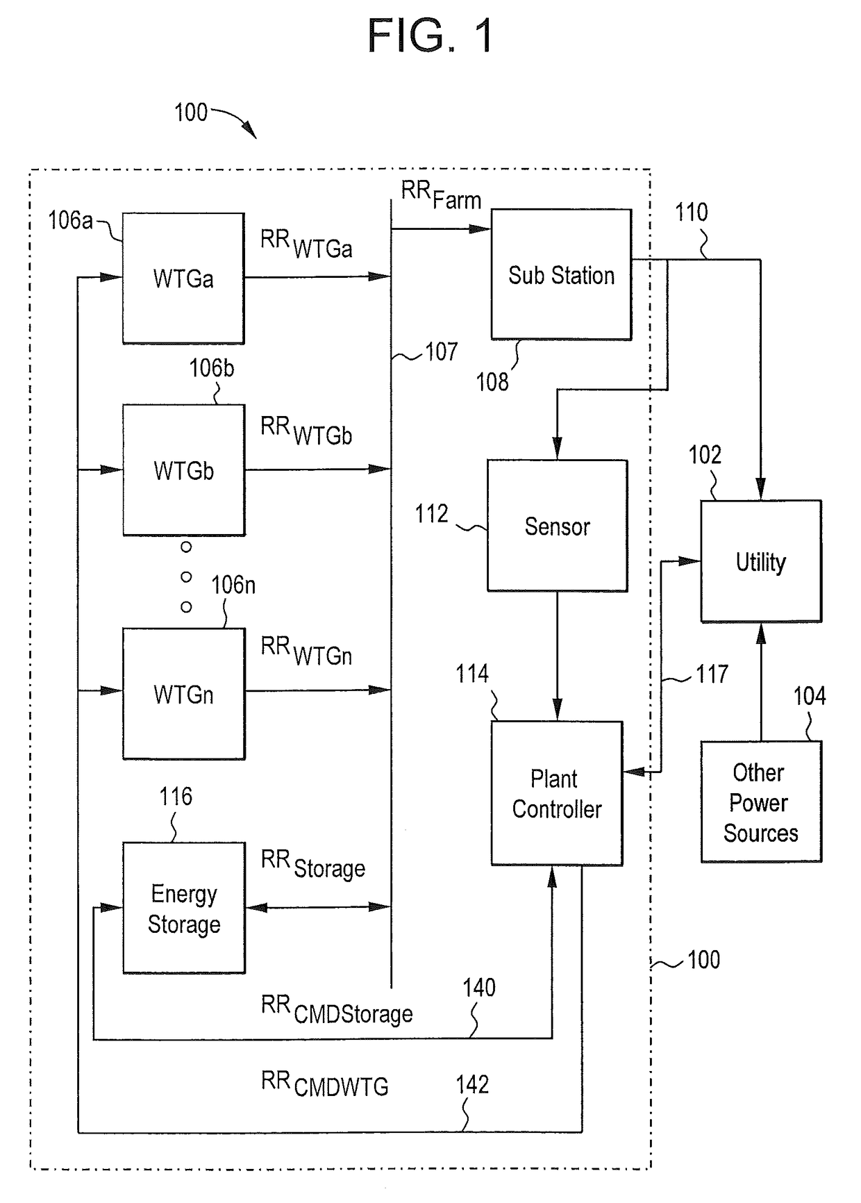
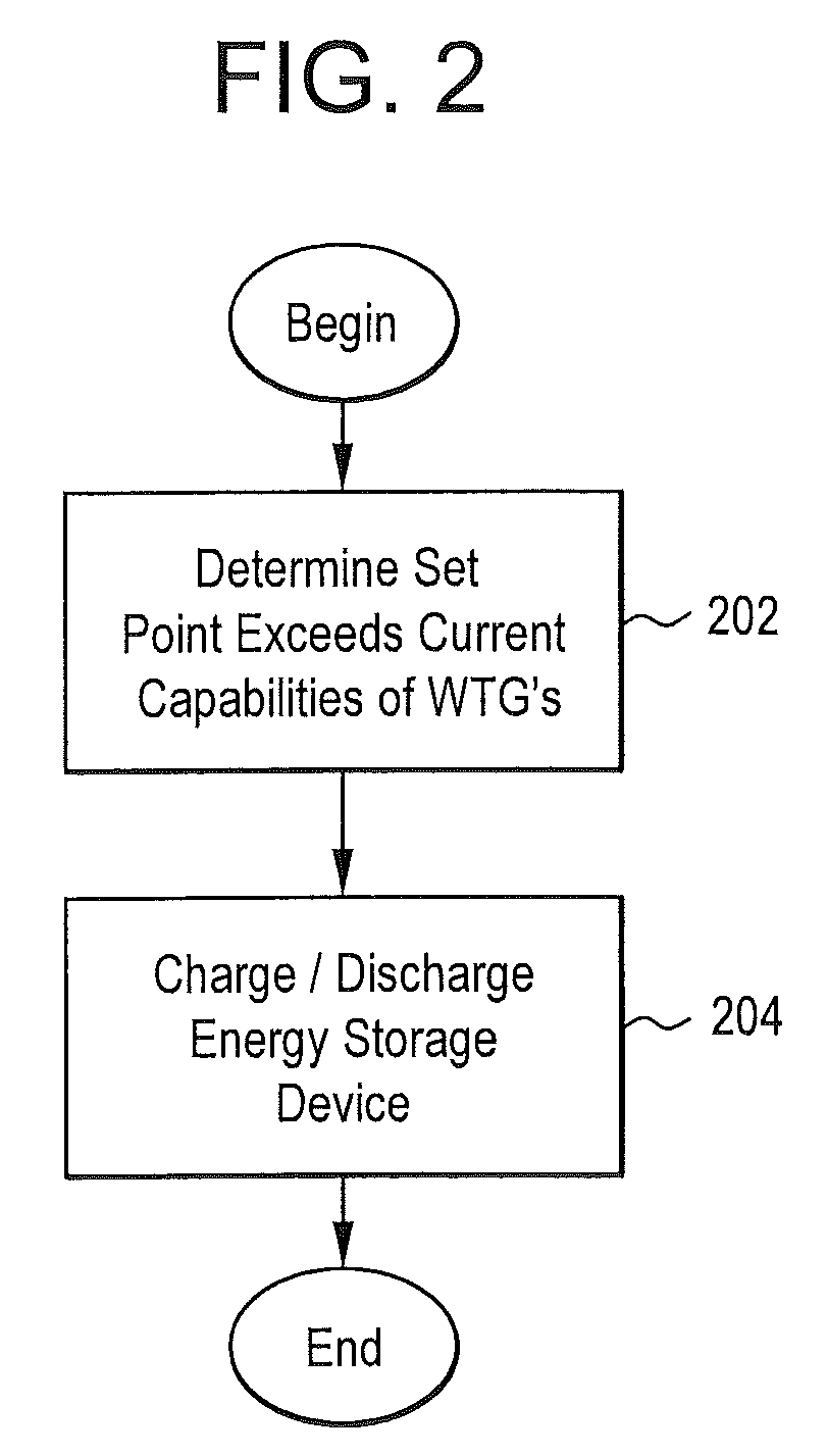
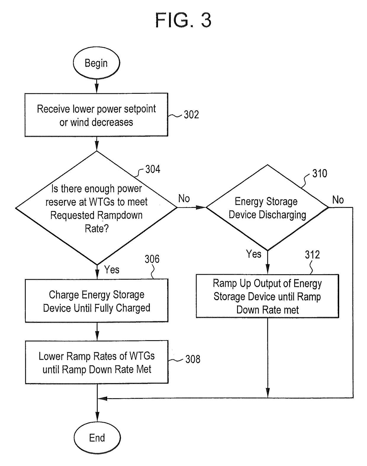
The invention provides a control system for an energy production facility that can manage power output to meet demand. The system includes a plant controller that can discharge energy storage when power reserves are not sufficient to meet the requested ramp down rate, or charge up energy storage when the power capability of the generators can meet the requested ramp down rate. The system also includes a wind farm with a power collection system and wind turbine generators, and an energy storage device coupled to the power collection system. The plant controller can cause the energy storage device to store energy when the rate of power production exceeds the output requirement and discharge energy when the rate of power production is below the requirement. The technical effects of this invention include improved management of power output and better utilization of energy storage in wind farms.

Problems solved by technology

Because instantaneous electrical generation and consumption must remain in balance to maintain grid stability, this variability can present substantial challenges to incorporating large amounts of wind power into a grid system.
Intermittency and the non-dispatchable nature of wind energy production can raise costs for regulation, incremental operating reserve, and (at high penetration levels) could require an increase in the already existing energy demand management and load shedding.
However these challenges are no different in principle to the substantial challenges imposed by other forms of generation such as nuclear or coal power, which can also show very large fluctuations during unplanned outages and have to be accommodated accordingly.
That is, there may be spikes in RRfarm caused by increases in wind rate that need to be avoided.
This, however, leads to the loss of power that could otherwise have been created by the wind turbine if running at a higher conversion rate.
However, in the event of a large decrease in wind, regardless of conversion efficiency, at present there may be no way to meet the power production demands.

Method used


Image

  • Power production control system and method
  • Power production control system and method
  • Power production control system and method

Examples


Embodiment Construction

[0021]Embodiments disclosed herein may provide an energy storage device to a power production facility. In one embodiment, the power production facility is a wind farm that includes wind turbine generators. Of course, the power production facility could be any type of power production facility and may include power production devices other than wind turbine generators. The energy storage device may store excess energy produced during times of high wind or when the required energy is less than what the wind farm is capable of producing given current wind conditions. This stored energy may be utilized, for example, during times of decreased wind to keep the level of RRfarm at or near a desired level. In addition, one embodiment allows the plant controller for the power production facility to communicate the total power available from both the power production devices and the energy storage device to the utility so that the utility may plan accordingly. In another embodiment, in the ev...


PUM


Abstract

A control system for an energy production facility includes a plant controller for receiving an indication of a measured power output of the energy production facility that includes power generators and produces output signals. The system also includes a processing unit operably coupled to the plant controller and responsive to executable computer instructions when executed on the processing unit cause the plant controller to: create an output signal that causes an energy storage device to discharge in the event power reserves of the power generators can not met the requested ramp down rate; and create an output signal that causes the energy storage device to charge up in the event that the power capability of the power generators can meet the requested ramp down rate.

Description

BACKGROUND OF THE INVENTION[0001]The subject matter disclosed herein relates to energy production and, in particular, to controlling energy production facilities in the presence of variable production capabilities.[0002]The production of energy in the form of electricity may take many forms. At the center of nearly all power stations is a generator, a rotating machine that converts mechanical energy into electrical energy by creating relative motion between a magnetic field and a conductor. The energy source harnessed to turn the generator varies widely. One energy source is wind.[0003]A wind farm is a group of wind turbines in the same location used for production of electric power. Individual turbines are interconnected with a medium voltage (usually 34.5 kV) power collection system and a communications network. At a substation, this medium-voltage electrical current is increased in voltage with a transformer for connection to the high voltage transmission system. The high voltage...

Claims


Application Information

Patent Timeline
Patent Type & Authority Patents(United States)
IPC IPC(8): H02K3/32
CPCF03D7/0284F03D7/048F03D9/005F03D9/02Y02E10/725F05B2270/1033F05B2270/337Y02E10/723F03D9/10F03D9/257Y02P90/50Y02E10/72Y02P80/20Y02E70/30
Inventor KIRCHNER, ANDREASUBBEN, ENNO
Owner GENERAL ELECTRIC CO
Learn More