Jar lid opener

a lid opener and jar technology, applied in the field of jar lid openers, can solve the problems of difficulty in opening the jar difficulty in adjusting the lid, etc., and achieve the effect of preventing corrosion

Inactive Publication Date: 2011-03-22
MITCHELL ELENA A
View PDF35 Cites 11 Cited by
  • Summary
  • Abstract
  • Description
  • Claims
  • Application Information

AI Technical Summary

Benefits of technology

[0014]An object of the jar lid opener is envisioned to engage an outer lip of a common lid used to seal a common jar and provide a venting means thereto the internal vacuum between the jar and the sealed lid easing the lid removal process.
[0015]Another object of the jar lid opener is made of a strong, durable metal such as a steel alloy or the like which will prevent corrosion.

Problems solved by technology

While such a storage method has worked well for years and will likely be around for many more years in the future, it is not without its disadvantages.
Perhaps the biggest of these disadvantages is the difficulty encountered when opening the jar for the first time.
However such aids still rely on physical strength and / or are not effective.
Such efforts are difficult and waste time for the even the strongest person, but those who are elderly, disabled, small in stature, or those with reduced diminished strength find the task impossible.
A particular problem arises from jars that have been used for canning.
Inserting a table knife between the lid and the glass container can cause the jar to break or at least chip, resulting in a possible injury.
These jars are difficult to open with available means such as a gripping pad.
Unfortunately, this design patent does not appear to be similar in appearance to the disclosed device, nor does it appear to disclose a jar lid opener that is capable of utilizing a hook and a handle to remove the vacuum from a jar before applying rotational force to a jar lid.
Unfortunately, this design patent does not appear to be similar in appearance to the disclosed device, nor does it appear to be capable of applying rotational torque to a jar lid.
Unfortunately, this patent does not appear to disclose a jar lid opener that comprises a hook that may be used to reduce pressure within a jar and to consequently make the application of rotational force to torque the jar lid open easier.
Unfortunately, this patent does not appear to disclose a jar lid opener that comprises an upper jaw assembly, a hook, and a handle to vent air into a jar and permit the application of rotational torque to open a jar lid.
Unfortunately, this patent does not appear to be similar in appearance to the disclosed device, nor does it appear to disclose a jar lid opener that is capable of utilizing a hook and a handle to remove the vacuum from a jar before applying rotational force to a jar lid.
Unfortunately, this patent does not appear to disclose a jar lid opener that comprises a hook that may be used to reduce pressure within a jar and to consequently make the application of rotational force to torque the jar lid open easier.

Method used


Image

  • Jar lid opener
  • Jar lid opener
  • Jar lid opener

Examples


embodiment 70

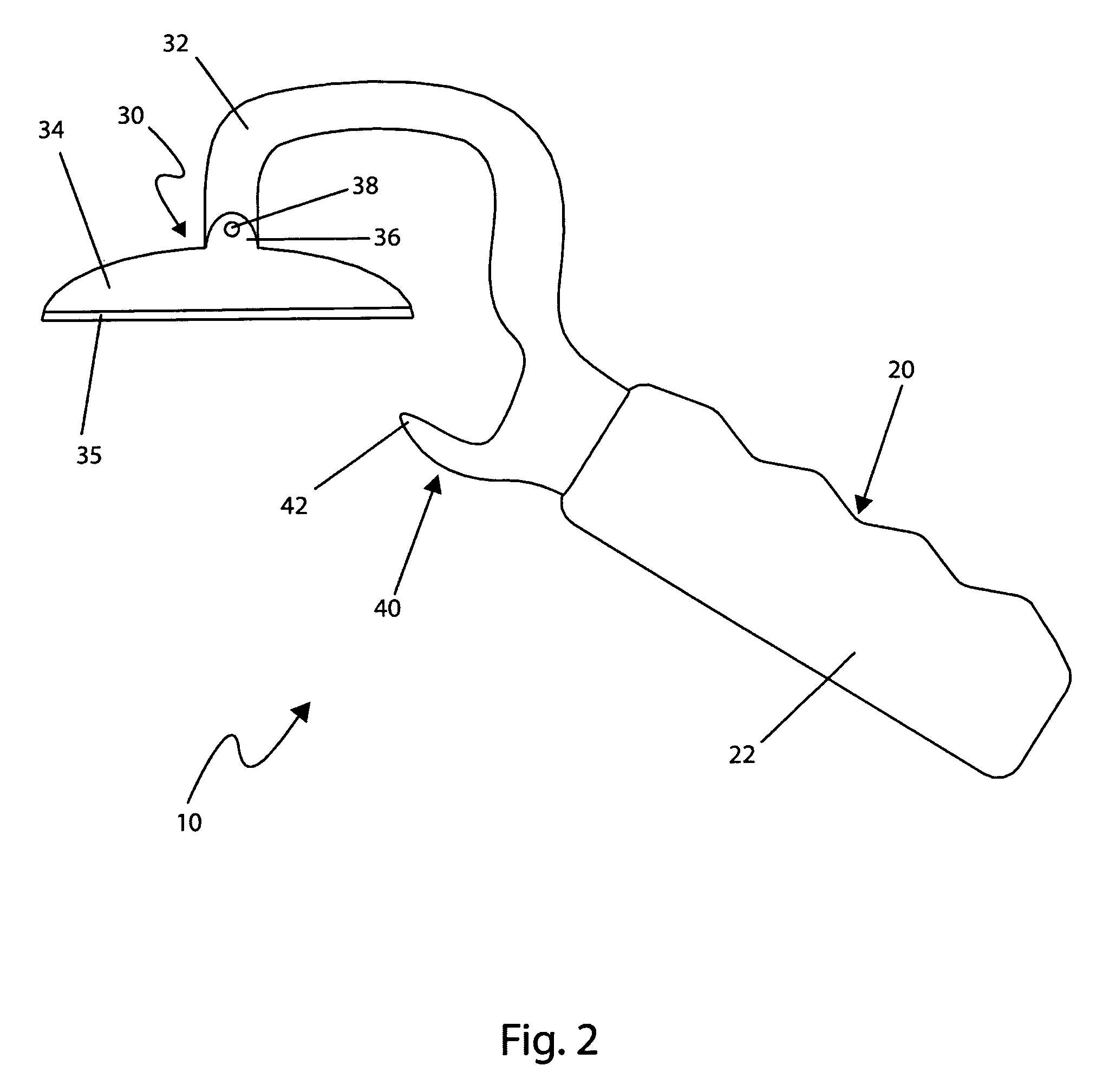
[0067]Referring finally to FIG. 5, an alternative embodiment of the present invention 10 comprises a rigid jar lid opener embodiment 70. The rigid jar lid opener 70 comprises similar materials and functions as the preferred embodiment 10 with particular enhancements including a rigid “C”-shaped body 74. The rigid “C”-shaped body 74 is similar to the preferred “C”-shaped body 32 including the preferred lower jaw 40 and hook 42 with particular enhancements including a rigid upper jaw 72. The rigid upper jaw 72 provides a permanent rigid attachment therebetween the rigid “C”-shaped body 74 and the rigid base 76. The rigid base 76 also Comprises a contact surface 35.

[0068]Referring finally to FIG. 6, an alternative embodiment of the present invention 10 comprises a rigid adjustable jar lid opener embodiment 80. The rigid adjustable jar lid opener 80 comprises similar materials and functions as the adjustable jar lid opener embodiment 50 with particular enhancements including an alternat...

embodiment 10

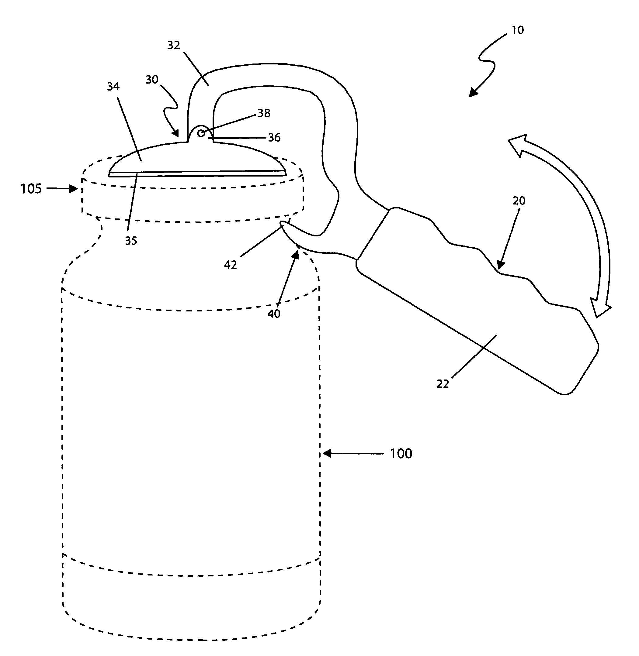
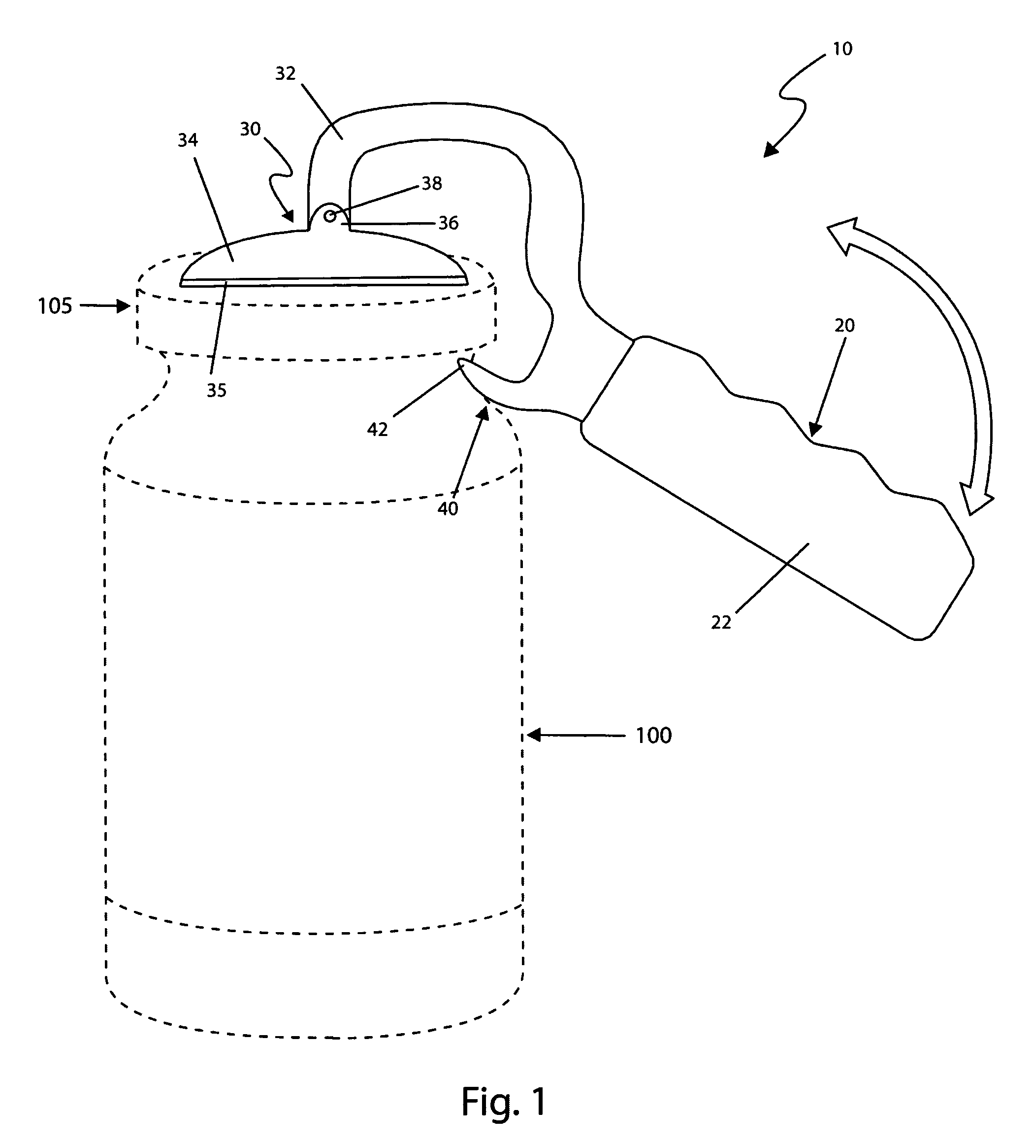
[0070]The alternate embodiments 70, 80 illustrated in FIGS. 5 and 6 are envisioned to provide repeated applications to a particularly sized container 100 with a common lid 105 having the same height and diameter. The alternate embodiments 70, 80 are envisioned to be introduced in a variety of sizes based upon a particular jar lid 105 design. The alternate embodiments 70, 80 are envisioned to provide certain economic and manufacturing advantages as compared to the preferred embodiment 10.

[0071]It is envisioned that other styles and configurations of the present invention can be easily incorporated into the teachings of the present invention, and only one particular configuration shall be shown and described for purposes of clarity and disclosure and not by way of limitation of scope.

[0072]The preferred embodiment of the present invention can be utilized by the common user in a simple and effortless manner with little or no training. After initial purchase or acquisition of the device...


PUM


Abstract

A device designed to aid in opening jars is herein disclosed, comprising a general form of a lever with a movable “C”-shaped jaw section. An upper jaw is designed to press down in the center area of a lid while a lower jaw presses upward on the edge or rim of the lid. In such a manner the device will break the seal of the jar and “pop” the lid. Once the seal has been broken, it is generally a simple issue to open the lid. An alternate embodiment provides for a lower adjustable section of the jaw which operates in a slip-joint manner similar to that of a pair of Channel-Lock® pliers to accommodate any size lid. The handle is fitted with a grip area for each finger and is covered with non-slip rubber to facilitate use and comfort. The device is generally small in size and can be easily stored in a kitchen drawer.

Description

RELATED APPLICATIONS[0001]The present invention was first described in a notarized Official Record of Invention on Dec. 5, 2007, that is on file at the offices of Montgomery Patent and Design, LLC, the entire disclosures of which are incorporated herein by reference.FIELD OF THE INVENTION[0002]The present invention relates generally to a device to aid in opening jars and, more particularly, to said device comprising an upper jaw designed to press down in a center area of a lid while a lower jaw presses upward on an edge or rim of the lid, thereby breaking a seal of the jar and making it easier for a user to open the lid.BACKGROUND OF THE INVENTION[0003]A great deal of food products are shipped and stored in glass jars with metal lids. While such a storage method has worked well for years and will likely be around for many more years in the future, it is not without its disadvantages. Perhaps the biggest of these disadvantages is the difficulty encountered when opening the jar for th...

Claims


Application Information

Patent Timeline
Patent Type & Authority Patents(United States)
IPC IPC(8): B67B7/16
CPCB67B7/20
Inventor MITCHELL, ELENA A.
Owner MITCHELL ELENA A
Why Eureka
Try Eureka