Energy storage system

a technology of energy storage and energy storage, applied in the direction of secondary cell servicing/maintenance, single ac network with different frequencies, safety/protection circuits, etc., can solve the problems of increasing weight and bulk, increasing the weight of batteries, and increasing the weight of electronic systems, so as to reduce the weight and physical size of electronic systems, and the operation period is longer.

Inactive Publication Date: 2011-03-22
NORTHERN LIGHTS SEMICON
View PDF8 Cites 20 Cited by
  • Summary
  • Abstract
  • Description
  • Claims
  • Application Information

AI Technical Summary

Benefits of technology

[0009]The present invention is directed to an energy storage system for electrical systems using magnetic capacitors. The present invention provides a longer period of operation than traditional systems and reduces the weight and physical size of electronic systems.
[0010]To achieve the foregoing objectives, and in accordance with the purpose of the present invention as broadly described herein, the present invention provides an energy storage system that includes a battery charger and energy storage devices. The battery charger is connected to a DC / AC current source. The energy storage devices are coupled between the battery charger and subsystems respectively. Each of the energy storage devices includes a magnetic capacitor (MCAP) and an over current protection device (OCPD). The battery charger charges the MCAPs, and the MCAPs supplies electric power to subsystems connected the energy storage devices. OCPDs detect current from MCAPs to subsystems and protect subsystems from excessive currents of voltages.

Problems solved by technology

However, many problems are associated with these architectures.
As a result, the battery is often very bulky and not optimized for continuous operations.
Large gauge wires are required to run between the battery and the high power draw subsystems, thus adding weight and bulk.
While it improves the efficiency and redundancy over single battery architecture, it adds bulk and weight to the system.
This problem is compounded by the use of batteries with different chemistries and charge / discharge profiles to better meet subsystem needs.
As a result, the system response and system weight are not greatly improved.
Furthermore, complex circuitries are required to maintain charge equalization in the ultra-capacitor banks, adding the weight and power management overheads.
All of these architectures are limited by the power / energy / weight / size characteristics of batteries.

Method used


Image

  • Energy storage system
  • Energy storage system
  • Energy storage system

Examples


Embodiment Construction

[0015]Reference will now be made in detail to the present preferred embodiments of the invention, examples of which are illustrated in the accompanying drawings. Wherever possible, the same reference numbers are used in the drawings and the description to refer to the same or like parts.

[0016]All figures are drawn for ease of explanation of the basic teachings of the present invention only; the extensions of the figures with respect to number, position, relationship, and dimensions of the parts to form the embodiment will be explained or will be within the skill of the art after the following description has been read and understood.

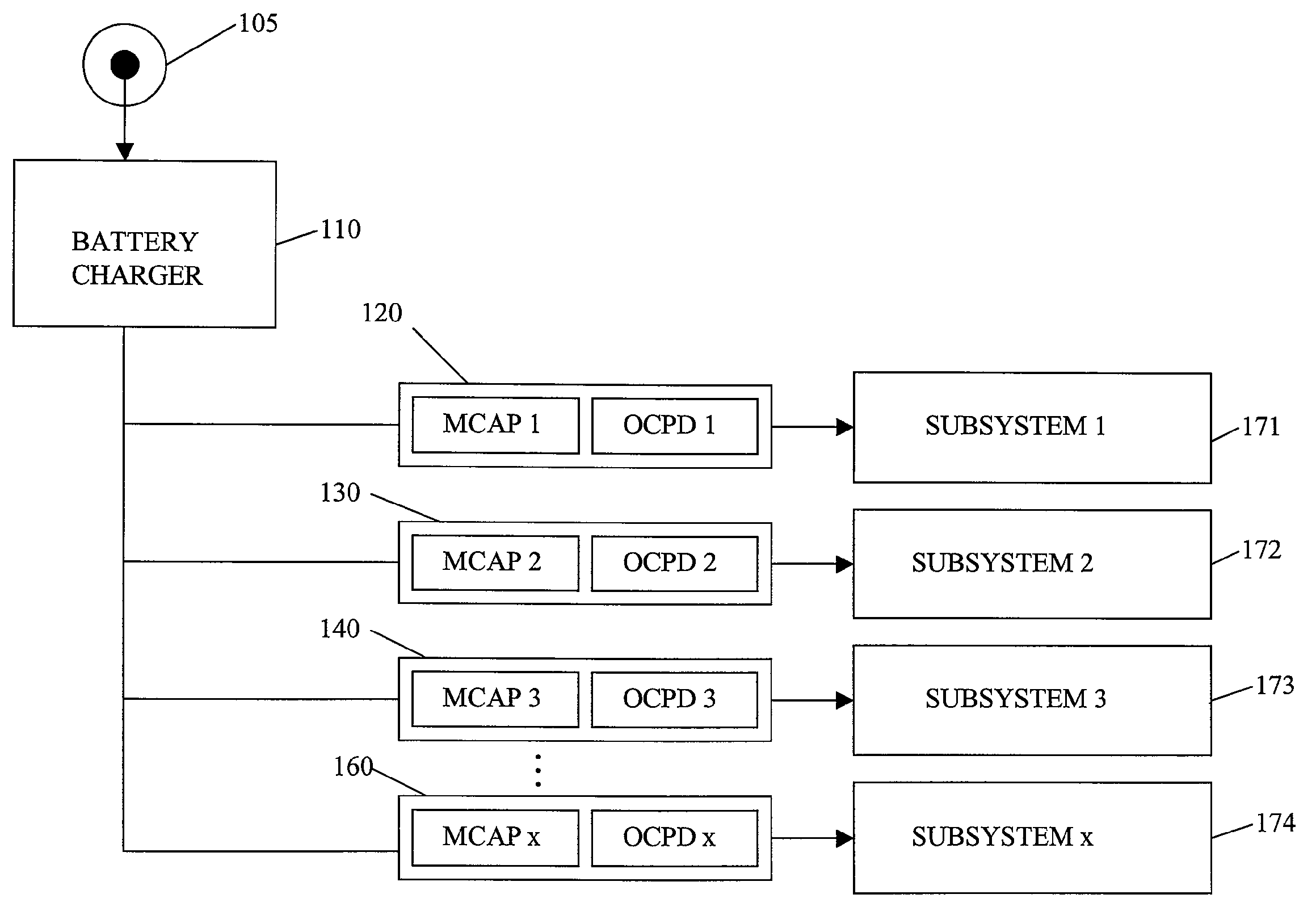
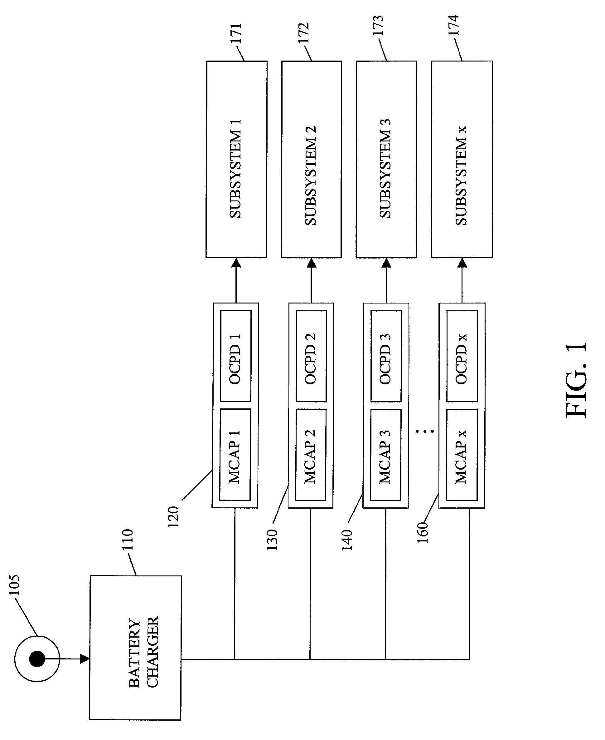
[0017]FIG. 1 shows a block diagram of a distributed energy storage system according to one preferred embodiment of this invention. An energy storage system includes a battery charger 110 and a plurality of energy storage devices 120, 130, 140, and 160. The battery charger 110 is connected to a DC / AC current source 105. The energy storage devices 120, 130...


PUM

PropertyMeasurementUnit
electric poweraaaaaaaaaa
poweraaaaaaaaaa
peak poweraaaaaaaaaa

Abstract

An energy storage system includes a battery charger and energy storage devices. The battery charger is connected to a DC / AC current source. The energy storage devices are coupled between the battery charger and subsystems respectively. Each of the energy storage devices includes a magnetic capacitor (MCAP) and an over current protection device (OCPD). MCAPs are charged by the battery charger and supply the electric power to subsystems connected the energy storage devices. OCPDs detect current from MCAPs to subsystems and protect subsystems from excessive currents of voltages.

Description

BACKGROUND[0001]1. Field of Invention[0002]The present invention relates to an energy storage system. More particularly, the present invention relates to an energy storage system with magnetic capacitors.[0003]2. Description of Related Art[0004]Most electronic systems are typically powered by chemical based batteries with a single power supply (single battery architecture). Newer “hybrid” architectures utilize a chemical based battery as the central power supply and ultra-capacitors / super-capacitors to supply peak power over a very short time duration (battery-ultracapacitor hybrid architecture). There are also battery based architectures that use multiple batteries (multiple batteries architecture).[0005]However, many problems are associated with these architectures. In single battery architecture, the battery must be sized to support both peak power draw and continuous energy draw. As a result, the battery is often very bulky and not optimized for continuous operations. Large gaug...

Claims


Application Information

Patent Timeline
Patent Type & Authority Patents(United States)
IPC IPC(8): H02J7/00H01G11/00H01M10/44H02J7/02
CPCH02J7/00H02J7/345H02J7/00304
Inventor LAI, JAMES CHYIFONG, KAI CHUN
Owner NORTHERN LIGHTS SEMICON
Why Eureka
Try Eureka