
Medical diagnostic X-ray apparatus provided with a cooling device

a technology of cooling device and x-ray apparatus, which is applied in the direction of x-ray tubes, radiation generation arrangements, applications, etc., can solve the problems of affecting the delicate balance of the treatment room, unable to allow the generation of heat, air or another cooling agent to be blown into the treatment room, etc., and achieves the effect of reducing the risk of cooling agent leakage, and reducing the risk of radiation radiation

Active Publication Date: 2011-03-22
KONINK PHILIPS ELECTRONICS NV
View PDF13 Cites 6 Cited by
  • Summary
  • Abstract
  • Description
  • Claims
  • Application Information

AI Technical Summary

Benefits of technology

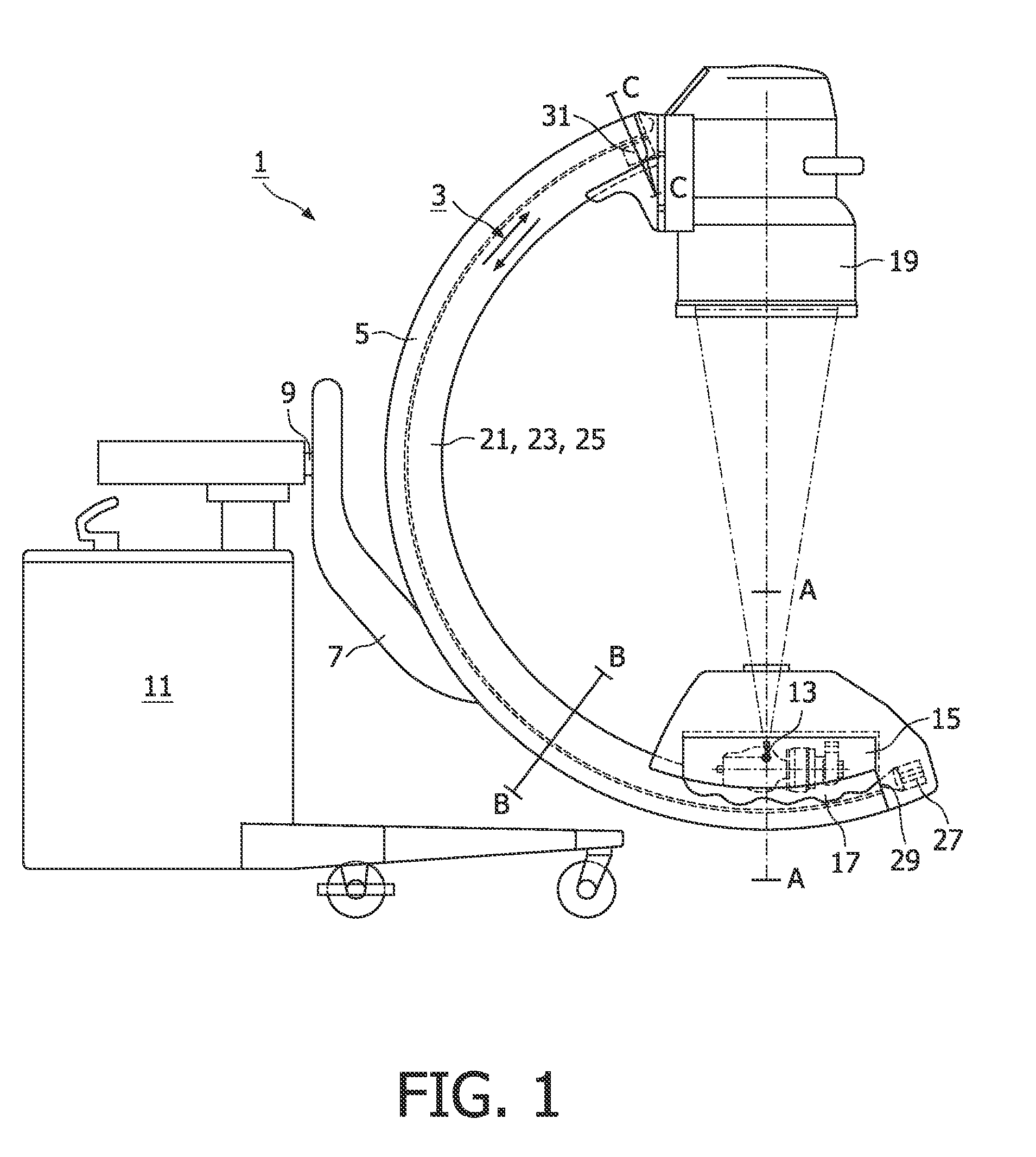
[0011]The object is achieved by a medical diagnostic X-ray apparatus in accordance with the invention, which is characterized in that the cooling agent is in direct thermal contact with the carrier. By dispensing with the use of cooling agent conduits, and by bringing the cooling agent in direct thermal contact with the carrier, the medical diagnostic X-ray apparatus in accordance with the invention employs in a direct and simple manner the relatively large thermal capacity and the large radiation surface of the carrier. The heat generated by the X-ray source during the production of X-rays is absorbed by the cooling agent, which transfers the heat to the carrier in a direct and efficient manner. The carrier subsequently transfers the heat to the surroundings of the X-ray apparatus. Efficient cooling of the X-ray apparatus is achieved by virtue of the absence of cooling agent conduits through which the cooling agent circulates and which extend partly through the interior of the carrier, the comparatively large thermal capacity and the large radiation surface of the carrier. In addition, the construction of the cooling device is simpler than the construction of the cooling device of the known X-ray apparatus due to the absence of cooling agent conduits extending partly through the interior of the carrier.
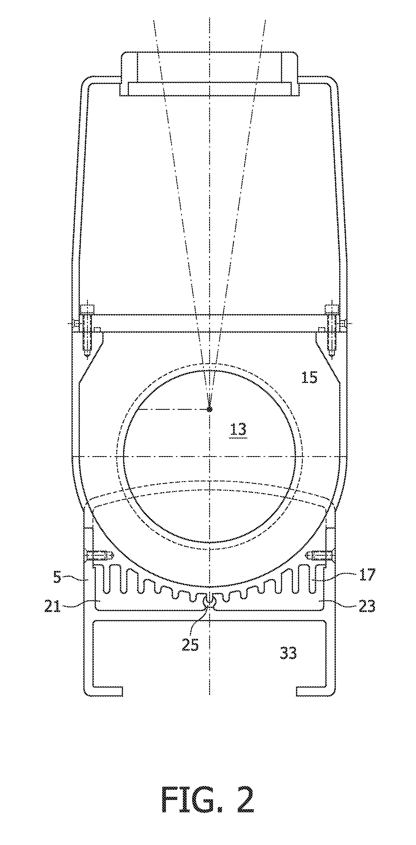
[0020]A further embodiment in accordance with the invention is a medical diagnostic X-ray apparatus, which is characterized in that the envelope is provided with cooling ribs. The use of cooling ribs causes the surface of the envelope around the X-ray source to be increased, leading to a further increase of the efficiency of the cooling device of the X-ray apparatus.

Problems solved by technology

During operation of an X-ray apparatus, the production of X-rays by the X-ray source causes the generation of much heat.
The use of X-ray apparatus with a cooling device causing air or another cooling agent to be blown into the treatment room is therefore not allowed.
A mass-change of the C-arm can disturb this delicate balance.

Method used


Image

  • Medical diagnostic X-ray apparatus provided with a cooling device
  • Medical diagnostic X-ray apparatus provided with a cooling device
  • Medical diagnostic X-ray apparatus provided with a cooling device

Examples


Embodiment Construction

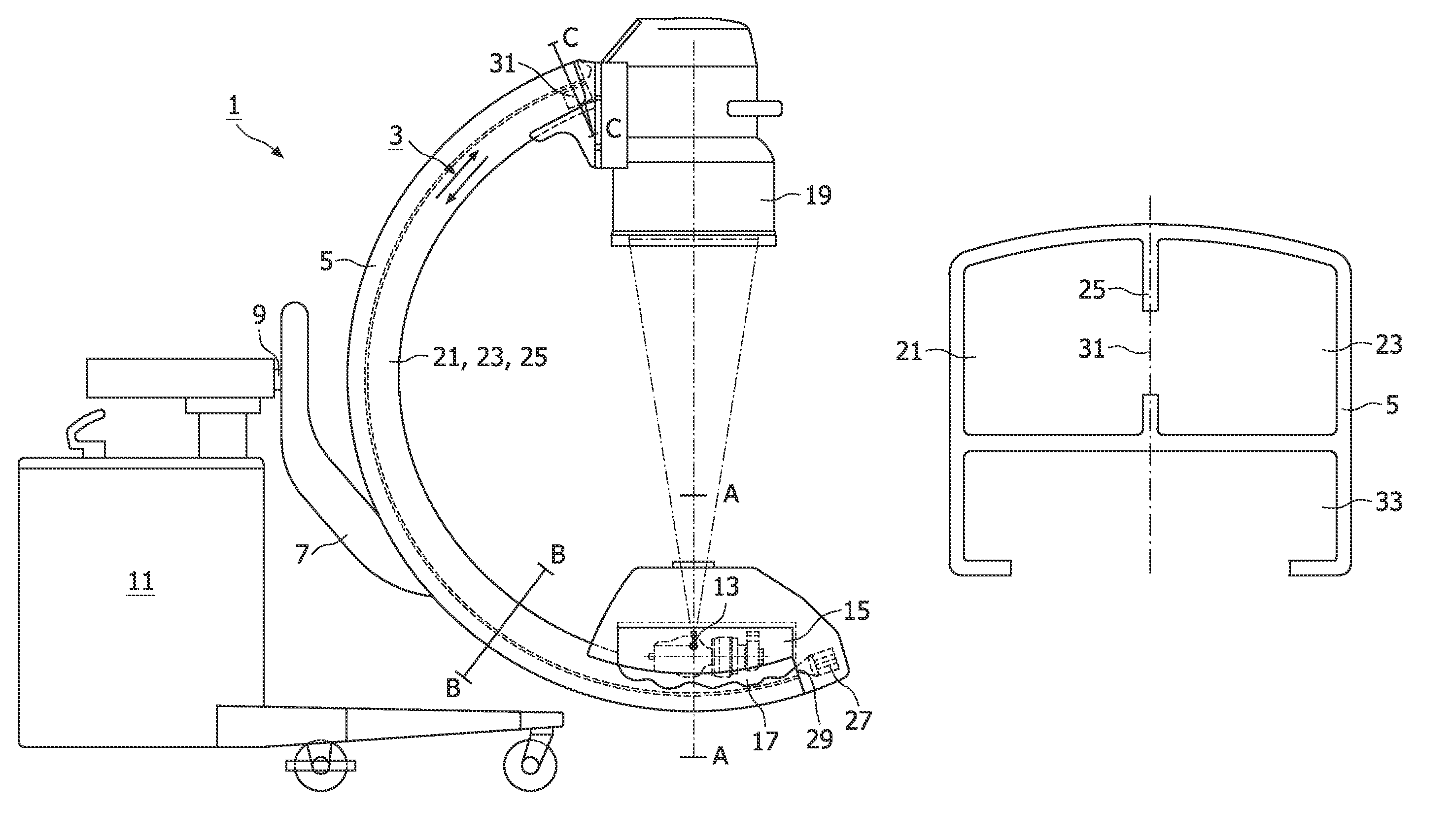
[0029]FIG. 1 is a diagrammatic side view of an exemplary embodiment of a medical diagnostic X-ray apparatus 1 provided with a cooling device 3 in accordance with the invention. In the exemplary embodiment shown, the X-ray apparatus 1 is provided with a rotatable carrier, i.e. a C-arm 5, and a frame 7 which guides the C-arm and with respect to which the C-arm 5 can be rotated. The frame 7 is rotatable about a horizontal shaft 9 and is connected, via this shaft 9, to a stand 11 which is movably located on the floor. At one end of the C-arm 5, there is an X-ray source 13 that is situated within an envelope 15 provided with cooling ribs 17. An X-radiation detector 19, in this case an image amplifier, is attached to the other end of the C-arm 5 so as to be diametrically opposite the X-ray source 13. By rotating the frame 7 about the horizontal shaft 9, and by rotating the C-arm 5 with respect to the frame 7, the X-ray source 13 and the X-radiation detector 19 can be positioned relative t...


PUM


Abstract

A medical diagnostic X-ray apparatus includes an X-ray source, a hollow carrier to which the X-ray source is connected, and a cooling device provided with a cooling device to cool the X-ray source during use of the X-ray apparatus. The cooling device is in direct thermal contact with the carrier, thus providing an efficient cooling mechanism for the X-ray source.

Description

FIELD OF THE INVENTION[0001]The invention relates to a medical diagnostic X-ray device[0002]comprising[0003]an X-ray source,[0004]a hollow carrier to which said X-ray source is connected,[0005]and a cooling device containing a cooling agent for cooling the X-ray source during operation of the X-ray apparatus.BACKGROUND OF THE INVENTION[0006]A medical diagnostic X-ray apparatus of the type mentioned in the opening paragraph is known from German Utility Model DE 295 10 802 U1. The known X-ray apparatus is an X-ray apparatus which is suitable for surgical applications. This X-ray apparatus is provided with a C-arm as a hollow carrier to which the X-ray source is connected, and has a cooling device comprising a double-walled envelope of the X-ray source. A cooling agent flows through the double-walled envelope of the X-ray source, said cooling agent being supplied through cooling agent conduits and being discharged by a cooling unit located outside the C-arm. The cooling unit, the cooli...

Claims


Application Information

Patent Timeline
Patent Type & Authority Patents(United States)
IPC IPC(8): H01J35/10H01J35/12
CPCA61B6/40A61B6/4441A61B6/4488H05G1/04H05G1/025A61B6/4405A61B6/4423
Inventor VAN DER ENDE, ADRIANUS
Owner KONINK PHILIPS ELECTRONICS NV
Learn More