Partial encapsulation of stents

a stent and encapsulation technology, applied in the field of medical devices, can solve the problems of restenosis of the vessel, high labor intensity of suturing, and in particular, and achieve the effects of preventing cellular infiltration, improving flexibility, and maintaining its shap

Inactive Publication Date: 2011-03-29
BARD PERIPHERAL VASCULAR
View PDF94 Cites 43 Cited by
  • Summary
  • Abstract
  • Description
  • Claims
  • Application Information

AI Technical Summary

Benefits of technology

[0008]It is also an object of this invention to provide a stent encapsulated to prevent cellular infiltration wherein portions of the stent can move during radial expansion without stressing or tearing the encapsulating material.
[0009]These and additional objects are accomplished by an encapsulation process that leaves portions of the stent free to move during expansion without damaging the ePTFE covering. The most basic form of this invention is produced by placing a stent over an inner ePTFE tube (e.g., supported on a mandrel) and then covering the outer surface of the stent with an outer ePTFE tube into which slits have been cut. The outer ePTFE tube is then laminated to the inner ePTFE tube through openings in the stent structure to capture the stent. By selecting the size and location of the slits, it is possible to leave critical parts of the stent unencapsulated to facilitate flexibility and expansion. Not only does the slit prevent capture of the underlying ePTFE, it forms a focal point for the ePTFE to flex. A more complex form of the process is to place over the stent an ePTFE sleeve into which apertures have been cut. This “lacey” outer sleeve leaves portions of the stent exposed for increased flexibility and for movement of the stent portions during expansion without damaging the ePTFE. Although a single stent can be used, these approaches lend themselves to use of a plurality of individual ring stents spaced apart along an inner ePTFE tube and covered by a “lacey” ePTFE sleeve.
[0010]In the present invention, individual ring stents are partially encapsulated using the procedure outlined above. Preferably, ring stents of zigzag sinusoidal structure are placed “in phase” (e.g., peaks and valleys of one stent aligned with those of a neighboring stent) on the surface of a tubular ePTFE graft supported by a mandrel. A sleeve of ePTFE is cut using CO2 laser so that openings are created, resulting in a “lacey” pattern. This “lacey” sleeve is then placed over the ring stents. The resulting structure is then subjected to heat and pressure so that regions of ePTFE become laminated or fused together where the lacey sleeve contacts the tubular graft. In addition, the ends of the stent can be completely encapsulated, by known methods, to stabilize the overall structure.

Problems solved by technology

However, stents are generally mesh-like so that endothelial and other cells can grow through the openings resulting in restenosis of the vessel.
This is partially because PTFE is extremely biocompatible causing little or no immunogenic reaction when placed within the human body.
However, such methods are far from ideal, and suturing, in particular, is very labor intensive.
However, such a monolithically encapsulated stent tends to be rather inflexible.
In particular, radial expansion of the stent may stress and tear the ePTFE.

Method used


Image

  • Partial encapsulation of stents
  • Partial encapsulation of stents
  • Partial encapsulation of stents

Examples


Embodiment Construction

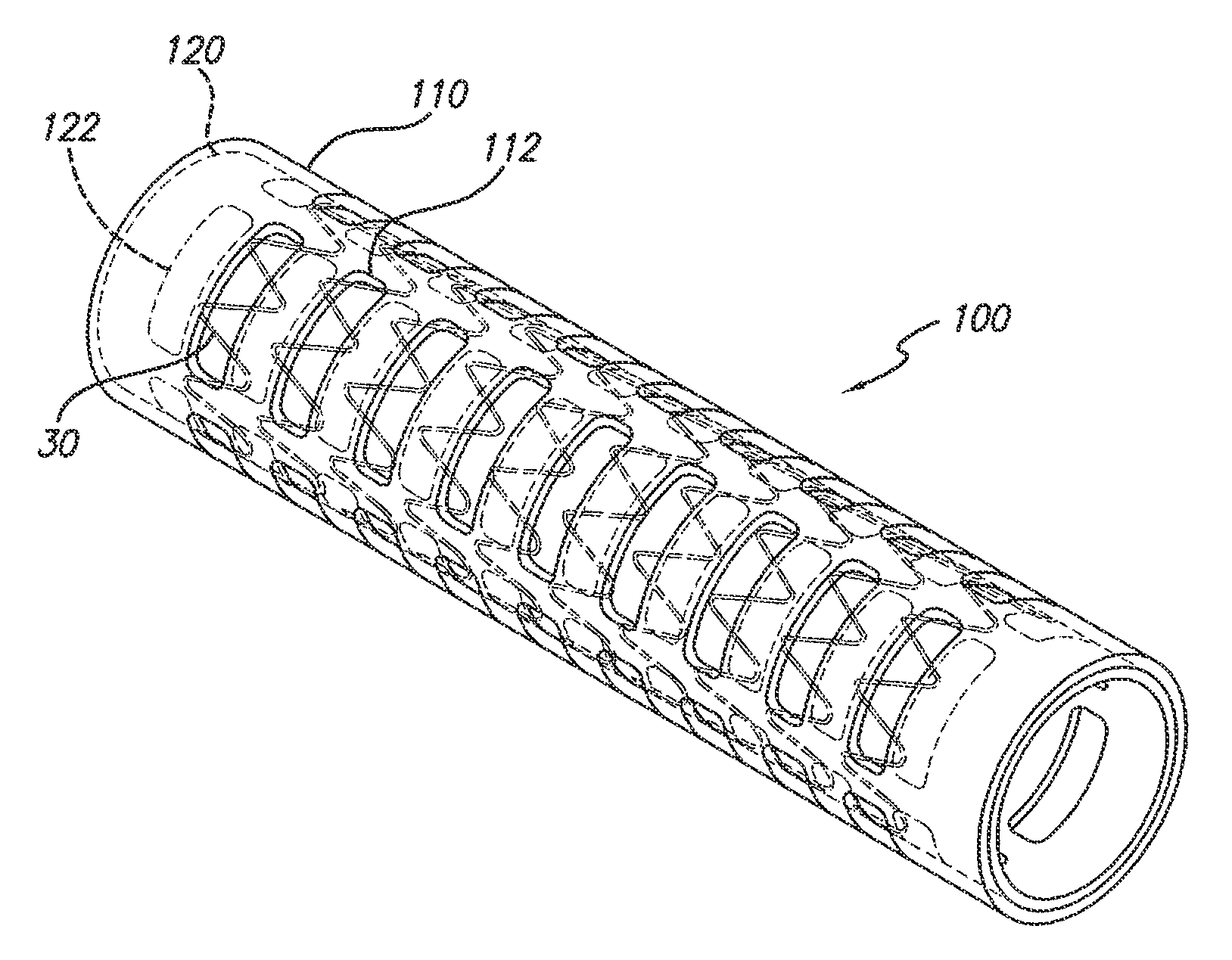
[0019]The present invention satisfies the need for an encapsulated stent device to prevent restenosis that is flexible upon expansion and contraction so that the general structural form is retained. This is accomplished encapsulating a stent or a plurality of stent rings using an ePTFE covering into which openings have been cut.

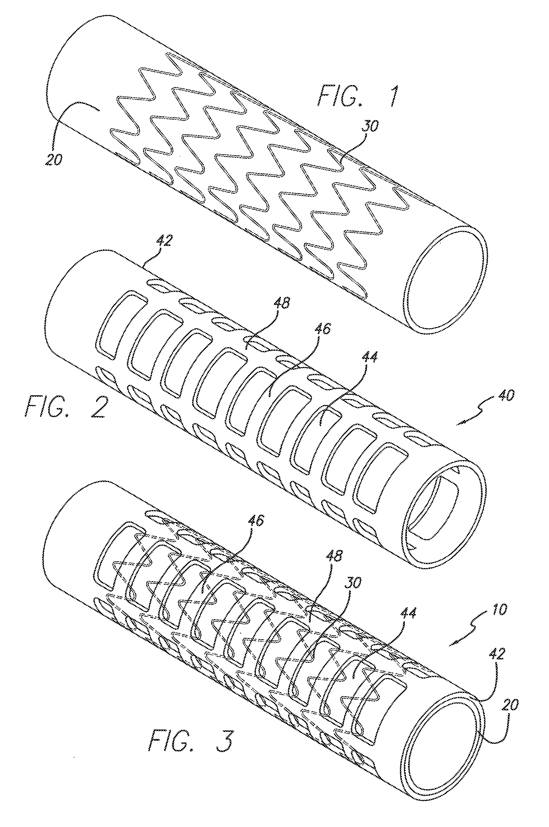
[0020]Referring now to the drawings, in which like reference numbers represent similar or identical structures throughout, FIG. 1 illustrates an initial step in constructing the partially encapsulated stent of the present invention. A tubular ePTFE graft 20 is placed over a mandrel for the assembly of a device 10 (FIG. 3). A stent is then placed over the graft 20. In a preferred embodiment, as shown in FIG. 1, a series of zigzag sinusoidal ring stents 30 are placed over the outer surface of the graft 20. Alternatively, one or more stents wherein each stent comprises more than one ring or hoop (e.g., where the rings are helically connected) can be used. The ri...


PUM

PropertyMeasurementUnit
lengthaaaaaaaaaa
biocompatibleaaaaaaaaaa
lengthaaaaaaaaaa

Abstract

A method of making an implantable medical device includes extruding a first ePTFE tube and a second ePTFE tube, cutting a plurality of slits in the first ePTFE tube, positioning a radially expandable support layer between the first and second ePTFE tubes so that the slits span portions of the support layer, and laminating the first ePTFE tube to the second ePTFE tube through openings in the support layer.

Description

PRIORITY[0001]This application is a divisional of U.S. patent application Ser. No. 10 / 873,062, filed Jun. 21, 2004, now abandoned, which is a divisional of U.S. patent application Ser. No. 09 / 848,740, filed May 3, 2001, now U.S. Pat. No. 6,770,087, which is a divisional of U.S. patent application Ser. No. 09 / 388,496, filed Sep. 2, 1999, now U.S. Pat. No. 6,398,803, which claims the benefit of U.S. Provisional Patent Application No. 60 / 118,269, filed Feb. 2, 1999. This application expressly incorporates by reference the entirety of each of the above-mentioned applications as if fully set forth herein.BACKGROUND[0002]The present invention relates generally to the field of medical devices, and more particularly, to encapsulation of stents.[0003]Stents and related endoluminal devices are currently used by medical practitioners to treat portions of the vascular system that become so narrowed that blood flow is restricted. Stents are tubular structures, usually of metal, which are radiall...

Claims


Application Information

Patent Timeline
Patent Type & Authority Patents(United States)
IPC IPC(8): B32B37/02A61F2/00A61F2/04A61F2/07
CPCA61F2/07A61F2/915A61F2002/072A61F2250/0029Y10S623/901Y10T156/1056Y10T156/109Y10T156/1062Y10T156/1026A61F2/89
Inventor LAYNE, RICHARD E.CUNDY, SANDRA M.BEBB, DEBRA A.
Owner BARD PERIPHERAL VASCULAR
Why Eureka
Try Eureka