Antenna component and methods

a technology of antenna components and components, applied in the field of small radio devices, can solve the problems of deteriorating the electric characteristics of the antenna, discrete matching components, and unsatisfactory matching,

Inactive Publication Date: 2011-03-29
CANTOR FITZGERALD SECURITIES
View PDF100 Cites 48 Cited by
  • Summary
  • Abstract
  • Description
  • Claims
  • Application Information

AI Technical Summary

Benefits of technology

[0009]The invention has the advantage that almost the entire antenna with its feed and matching circuits can be designed and tested as a whole of its own. This results in good reproducibility and better performance of the antenna compared to the situation that parts of the antenna structure would be on the circuit board of the radio device. In addition, the invention has the advantage that the design of the circuit board of the radio device is simplified, because the antenna matching need not be taken into account in it. What is required is only to reserve a space for the antenna component on the board and to provide contact surfaces on the board for connecting the antenna component. Furthermore, the invention has the advantage that possible later changes in the antenna are relatively simple and cheap, because the main circuit board of the radio device need not be renewed. A further advantage of the invention is that the auxiliary circuit board of the antenna component can also function as an integration base for possible additional components having an effect on the operation of the antenna. In addition, the invention has the advantage that the antenna is small as compared e.g. to an air-insulated planar antenna operating in the same frequency range.
[0010]In another aspect of the invention an antenna component useful as part of an antenna is disclosed. In one embodiment, the antenna comprises a dielectric antenna, and the component comprises: at least one radiation element having a dielectric substrate and an antenna radiator; and an auxiliary board comprising a conductor pattern adapted to feed the radiator and to match the antenna, the conductor pattern comprising an antenna feed conductor and at least one ground conductor disposed substantially proximate the feed conductor for connection to a signal ground. The radiation element is fastened to the auxiliary board, the radiator being electrically coupled to the conductor pattern.
[0011]In one variant, the auxiliary board comprises a single layer circuit board, or alternatively a multi-layer circuit board.
[0012]In another variant, the at least one ground conductor comprises two conductors, one on each side of the feed conductor and at substantially the same level therewith.
[0013]In still another variant, the at least one ground conductor comprises two conductors, one disposed at least partly above the feed conductor, and the other disposed at least partly below the feed conductor.
[0014]In yet a different variant, a majority portion of the radiator is disposed on a front surface of the radiation element, and the radiator is galvanically connected both to the feed conductor and the at least one ground conductor. The radiator also extends to an upper surface of the radiation element.

Problems solved by technology

In order to reduce the size of the antenna, this distance can be made very small, but a harmful result of this is the deterioration of the electric characteristics of the antenna.
However, the matching can be unsatisfactory in a part of the operating band of the antenna, in which case it is necessary to use separate matching components, in addition, in the feed circuit of the antenna.
Discrete matching components increase the production costs of the antenna.
In addition, the reproducibility of the antenna unit is poor because of the tolerances of the component values.
This results in a need to tune the antenna, which again has its own practical difficulties.

Method used


Image

  • Antenna component and methods
  • Antenna component and methods
  • Antenna component and methods

Examples


Embodiment Construction

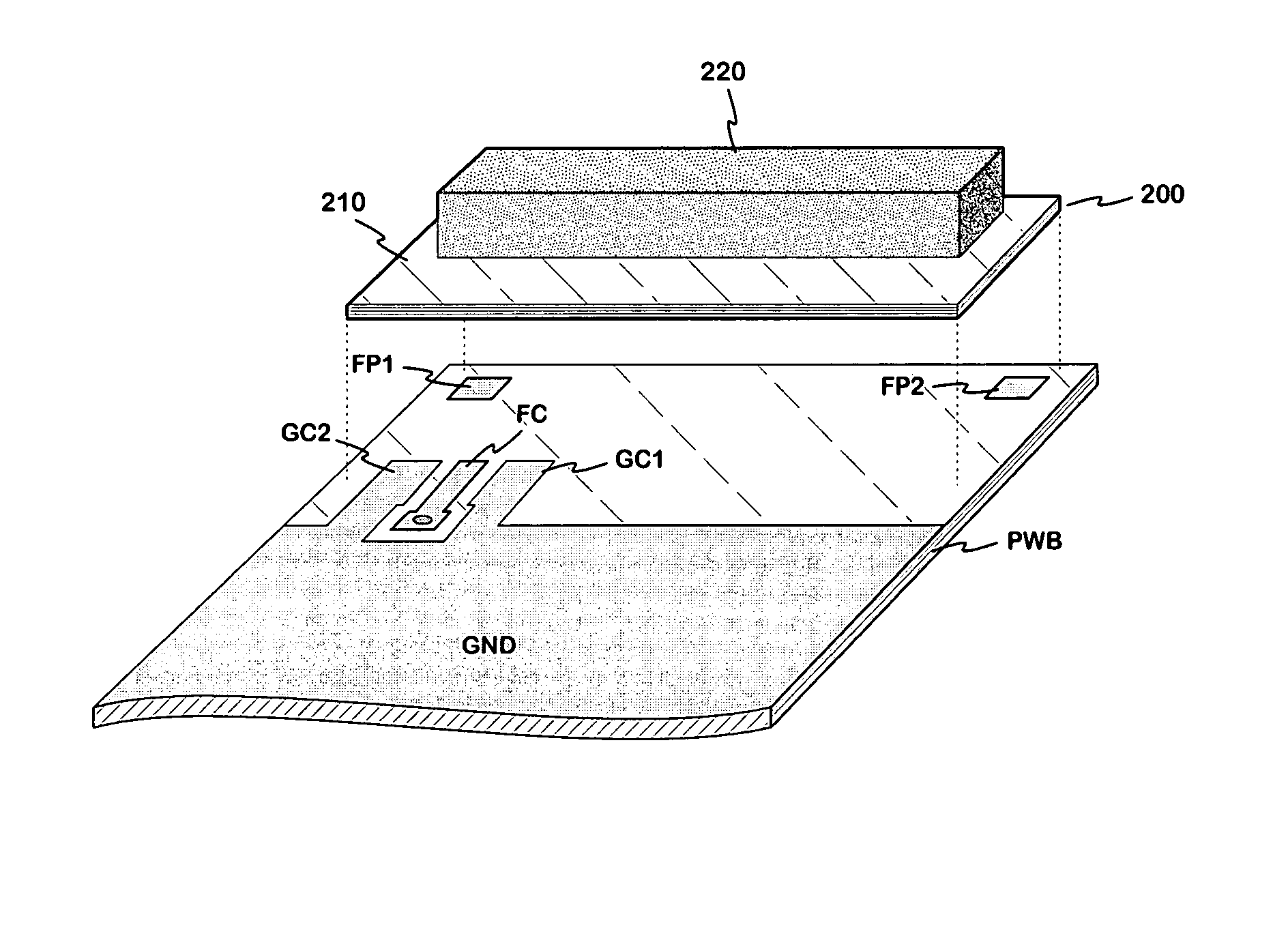
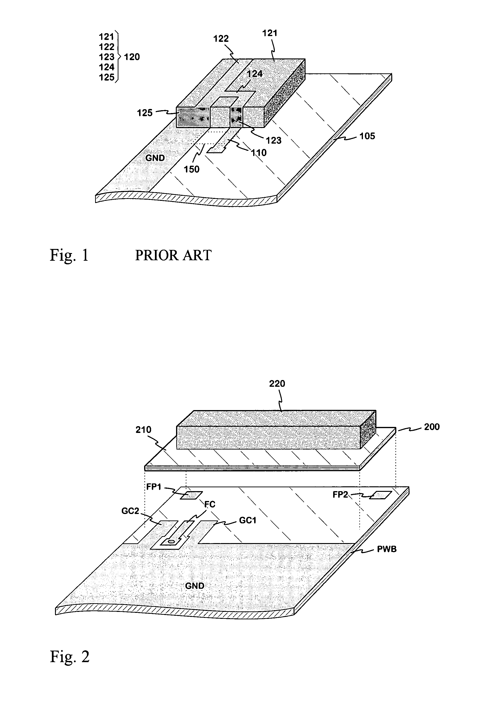
[0040]FIG. 2 is a schematic drawing of the principle of the antenna component according to the invention and of the circuit board of the radio device, on which circuit board the antenna component is intended to be mounted. The antenna component 200 is shown in the drawing above its mounting place. The antenna component has two main parts: an auxiliary board 210 and a radiation piece 220. The auxiliary board is a small circuit board, which is primarily for the matching of the antenna. The antenna conductors belonging to the auxiliary board form a conductor pattern, which is advantageous with regard to the matching. The antenna conductors can be on the surface of or inside the board. In the latter case, the auxiliary board is a multilayer board, which again can be based on ordinary circuit board material or it can be a ceramic board manufactured by the LTCC (Low Temperature Co-fired Ceramic) technique. The radiation piece comprises a dielectric chip and a conductor radiator on its sur...


PUM


Abstract

An antenna component suited for small-sized radio devices for forming a dielectric antenna. A small auxiliary circuit board (210) is used for the matching of the antenna, the matching being based on a conductor pattern on it. A substrate chip (220), on the surface of which the radiator is, and the auxiliary board are fastened to each other, whereby the radiator is electrically connected to said conductor pattern. The radiator, its substrate and the auxiliary board form a unitary, solid antenna component (200), which is mounted on the circuit board (PWB) of the radio device. The antenna with its feed and matching circuits can be designed and tested as a whole of its own, in which case the reproducibility is good. In the design of the circuit board of the radio device, the antenna needs to be taken into account only by reserving a space for the antenna component on the circuit board.

Description

PRIORITY AND RELATED APPLICATIONS[0001]This is a continuation application of and claims priority to International PCT Application No. PCT / FI2005 / 050382 having an international filing date of Oct. 27, 2005, which claims priority to Finland Patent Application No. 20041455 filed Nov. 11, 2004, each of the foregoing incorporated herein by reference in its entirety. This application is related to co-owned U.S. Pat. No. 7,589,678, issued Sep. 15, 2009 and entitled “Multi-Band Antenna With a Common Resonant Feed Structure and Methods”, and co-owned U.S. Pat. No. 7,663,551, issued Feb. 16, 2010 and entitled “Multiband Antenna Apparatus and Methods”, each also incorporated herein by reference in its entirety. This application is also related to co-owned U.S. Pat. No. 7,786,938, issued Aug. 31, 2010 and entitled “Antenna, Component And Methods”, and U.S. Pat. No. 7,679,565, issued Mar. 16, 2010 and entitled “Chip Antenna Apparatus and Methods”, both of which are incorporated herein by referen...

Claims


Application Information

Patent Timeline
Patent Type & Authority Patents(United States)
IPC IPC(8): H01Q1/38H01QH01Q5/00H01Q5/371H01Q9/04H01Q21/28H05K1/14
CPCH01Q1/38H01Q9/0421H01Q5/371H01Q21/28H05K1/141
Inventor KOSKINIEMI, KIMMOKURONEN, VESA
Owner CANTOR FITZGERALD SECURITIES
Why Eureka
Try Eureka