Multi-path rotary wing aircraft gearbox

a multi-path, rotary wing technology, applied in mechanical equipment, transportation and packaging, gearing, etc., can solve the problems of still requiring a relatively large volume system of relatively significant weight, many conventional and split-torque gearbox systems are somewhat heavy and voluminous, etc., to achieve significant torque transfer, reduce weight, and reduce packaging size

Inactive Publication Date: 2011-04-05
SIKORSKY AIRCRAFT CORP
View PDF18 Cites 11 Cited by
  • Summary
  • Abstract
  • Description
  • Claims
  • Application Information

AI Technical Summary

Benefits of technology

[0009]Each split torque module is driven by a high-speed input shaft from a gas turbine engine. At the first stage, the input shaft rotates about an input shaft axis of rotation and mounts a bevel pinion gear that engages a bevel face gear at a first bevel gear mesh. The bevel face gear is mounted to a first stage shaft which rotates about the axis of rotation. The first stage shaft is located above and at least partially within the perimeter of a final output gear to provide a compact packaging arrangement.
[0011]At the second stage, a multitude of quill shaft assemblies are mounted for rotation about respective axes adjacent the perimeter of the final stage output gear. Such an arrangement permits each quill shaft assembly to be mounted in a single common plane such as is readily provided by a relatively flat gearbox housing. The quill shaft assemblies rotate at an equivalent speed and include a quill shaft that is torsionally flexible and angularly compliant to provide the required gear timing for gearbox assembly yet maintain a proper load distribution during gearbox operation. The quill shaft assemblies, as part of the second stage of reduction, provide equal load balance between all gears engaged in the power train.
[0012]At the third stage, each quill shaft assembly includes a first and second helical spur gear in meshing engagement with the final output gear. Each torque split module thereby transfers the power from the single high speed input shaft into a multiple of meshing engagements with the final output gear to provide significant torque transfer typically desired in a heavy lift rotary wing aircraft embodiment within a relatively flat gearbox system to provide multiple load paths in which the failure of a single module will not fail the entire system.
[0013]The present invention therefore provides a split torque multi-path gearbox system that is relatively uncomplicated and inexpensive to manufacture, has a reduced weight and packaging size, assures an even split of loads, includes independent redundant load paths, yet provides inherent adaptability to various aircraft platforms.

Problems solved by technology

While this prior art split torque system has managed to increase the horsepower-to-weight ratio in some situations, especially where total horsepower involved is substantial and where multiple input drive paths from different engines are present, this conventional approach still requires a relatively large volume system of relatively significant weight.
Many conventional and split-torque gearbox systems are somewhat heavy and voluminous due to unequal load sharing.
Unequal load sharing results when the gearbox system does not consistently split the load.
Furthermore, although effective, typical split torque gearbox systems are usually designed for a single aircraft platform due to the relatively large volume necessarily inherent in these conventional designs.

Method used


Image

  • Multi-path rotary wing aircraft gearbox
  • Multi-path rotary wing aircraft gearbox
  • Multi-path rotary wing aircraft gearbox

Examples


Embodiment Construction

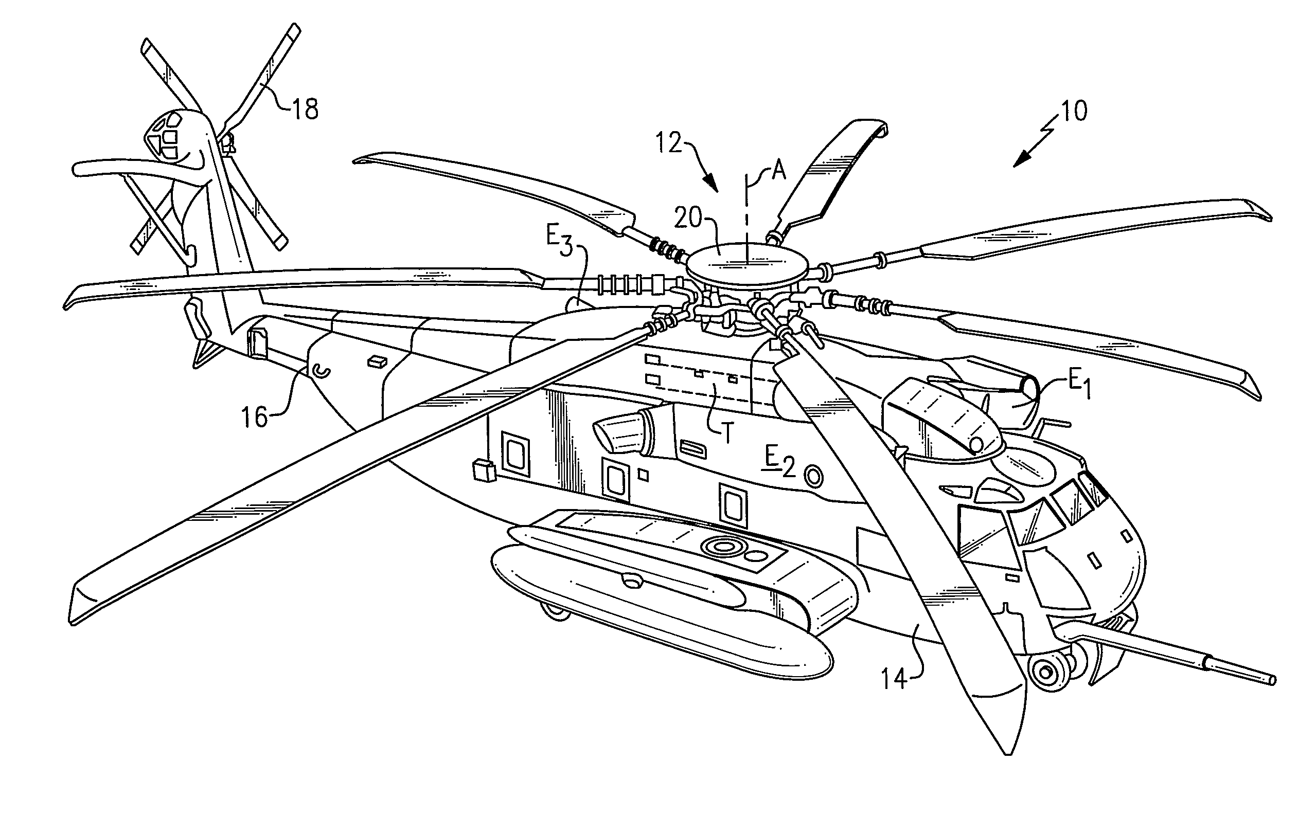
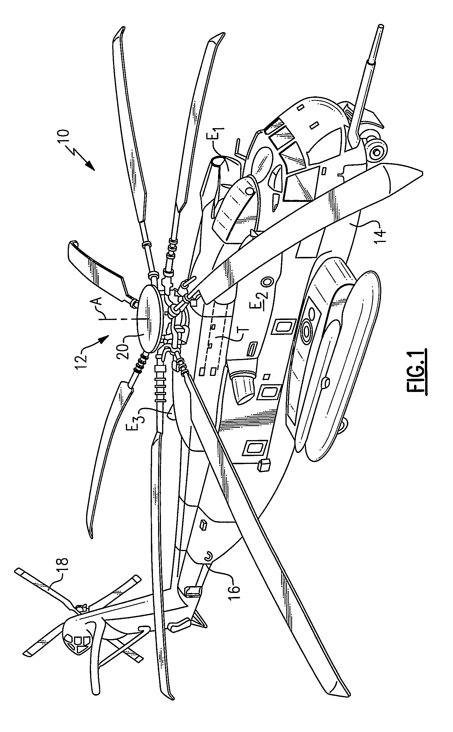
[0023]FIG. 1 schematically illustrates a rotary-wing aircraft 10 having a main rotor assembly 12. The aircraft 10 includes an airframe 14 having an extending tail 16 which mounts an anti-torque rotor 18. The main rotor assembly 12 is driven about a rotor axis of rotation A through a gearbox system 20 by one or more engines E. It should be understood that a Sikorsky CH-53 type helicopter configuration as illustrated in the disclosed embodiment is for discussion purposes only and other aircraft will also benefit from the present invention.

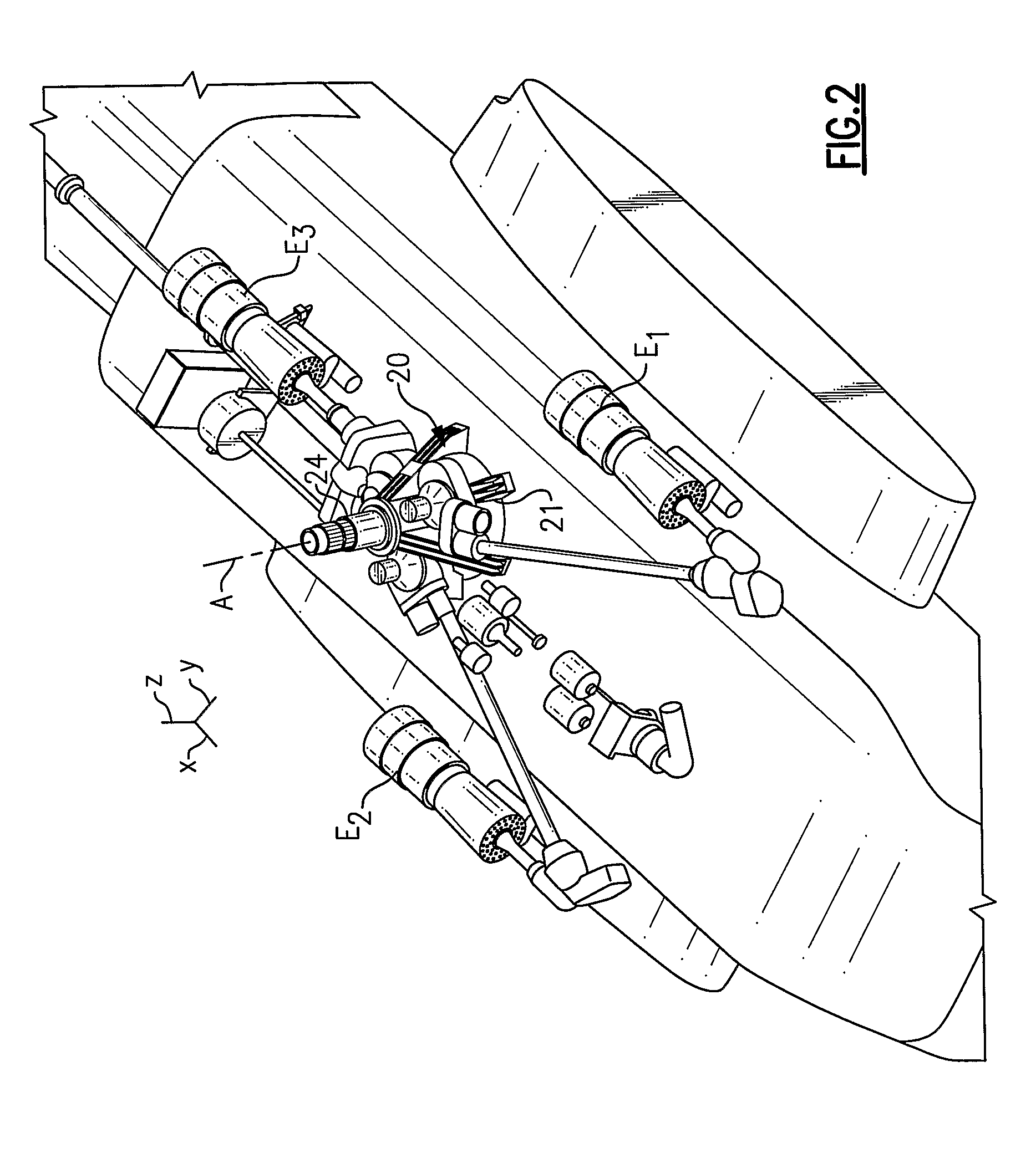
[0024]Referring to FIG. 2, the gearbox system 20 is a split torque, three stage power gear train that transmits torque from a multitude of high-speed engines E to a main rotor shaft 24 of the main rotor assembly 12. The gearbox system 20 is preferably mounted within a housing 21 which supports the geartrain therein as well as a main rotor shaft 24. It should be understood that various support housing and structural arrangements will be usable with th...


PUM


Abstract

A multi-path split torque gearbox system provides a multiple of three stage torque split power gear trains modules that each transmits torque from a high-speed engine to a main rotor shaft (36). The first stage bevel gear arrangement (30,32) provides a compact packaging arrangement that facilitates various engine mounting locations in all axes. At the second stage, quill shaft assemblies (40) provide equal load balance. At the third stage, each quill shaft assembly includes a multiple of pinion gears (48) in meshing engagement with the final output gear (28). Each torque split modules transfer the power from the high speed input shaft into a multiple of meshing engagements with the final output gear to provide significant torque transfer desired in a single rotor heavy lift rotary wing aircraft embodiment within a compact housing package.

Description

STATEMENT REGARDING FEDERALLY SPONSORED RESEARCH OR DEVELOPMENT[0001]This invention was made with government support with the United States Navy under Contract No.: N00019-06-C-0081. The government therefore has certain rights in this invention.BACKGROUND OF THE INVENTION[0002]The present invention relates to a multi-path gearbox, and more particularly to a multi-path torque split gearbox for an aircraft.[0003]A gearbox system transfers power from a gas turbine engine to a rotor or propeller of an aircraft. A typical system may direct power from several turbine engines to a single rotor or propeller. Since the rotational velocity of the rotor or propeller is significantly lower than the rotational velocity of the gas turbine engine, the gas turbine engine rotational velocity must be reduced by the gearbox system. In reducing the rotational velocity of the gas turbine engine output, torque is increased through a series of intermediate gear stages and shafts, before the final output d...

Claims


Application Information

Patent Timeline
Patent Type & Authority Patents(United States)
IPC IPC(8): F16H37/06
CPCB64C27/14F16H1/22Y10T74/19051Y10T74/1906
Inventor GMIRYA, YURIY
Owner SIKORSKY AIRCRAFT CORP
Why Eureka
Try Eureka