Suction coring device and method

a technology of suction coring and cores, which is applied in the direction of directional drilling, mechanical machines/dredgers, and well accessories. it can solve the problems of limited supply, limited size (diameter and length) of cores, and limited penetration of gravity assisted drop corers, etc., and achieves low cost, convenient operation and handling, and low cost.

Inactive Publication Date: 2011-04-05
FOLEY ALAN
View PDF25 Cites 11 Cited by
  • Summary
  • Abstract
  • Description
  • Claims
  • Application Information

AI Technical Summary

Benefits of technology

[0008]The present invention provides improved devices and methods for obtaining cores from a sea bed and retrieving them to the water surface. The suction corer of the present invention provides an inexpensive, portable system to obtain sediment cores from the sea bed. In addition, the suction corer of the present invention is simple to operate and handle and provides a means for retrieving large volumes of sediment from the sea floor. The suction corer can be operated from one of the smaller surface vessels that are in general use in offshore operations and are available at moderate cost. In preferred configurations, the suction corer is similar in dimensions to a survey AUV (autonomous underwater vehicle), such as the Hugin 3000 AUV, a generally about 1 meter in diameter and around 6 meters in length. The small size and weight will allow the suction corer to be launched and operated from an AUV support ship with little modification.
[0010]In a preferred embodiment, the suction corer devices and methods of the present invention include a coring locator system which allows the suction corer to be redeployed multiple times to the same general location or core hole. Thus, the suction corer can re-enter the same core hole and core to additional depth within. This method allows cores to be taken at depths that are multiples of the length of the suction corer body.
[0011]In another preferred embodiment of the invention, an extended suction coring device is constructed using a plurality of individual suction corer bodies that are concatenated together. This is preferably done at the surface vessel as the corer device is deployed into the water. This technique provides a single coring device having a currently preferred extended length that is 3-5 times that of a single coring device section. The extended suction coring device is useful in situations wherein it is desired to sample in extremely soft sediments in a single coring run and avoid the problem of hole collapse and the need to case the core hole with multiple strings of casing.

Problems solved by technology

Among the disadvantages of existing systems and current practice is the limited penetration of gravity assisted drop corers, limited size (diameter and length) of cores due to restricted retrieval winch capacity and lack of attitude control for a drop corer.
However, these devices require dynamically positioned (DP) surface vessels for support.
DP vessels are expensive and in limited supply.
In addition, the drilling rigs themselves are costly to operate and maintain.

Method used


Image

  • Suction coring device and method
  • Suction coring device and method
  • Suction coring device and method

Examples


Embodiment Construction

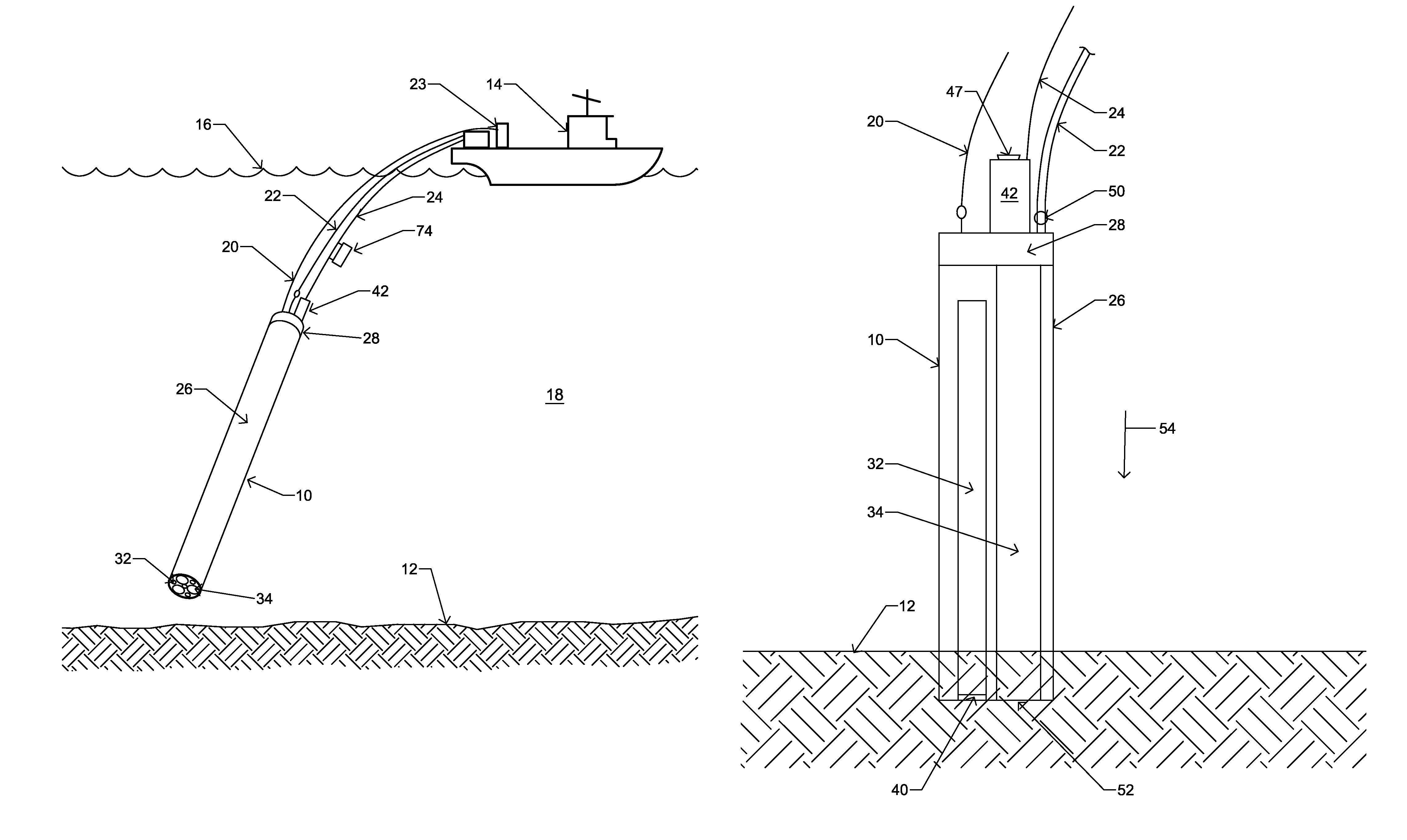
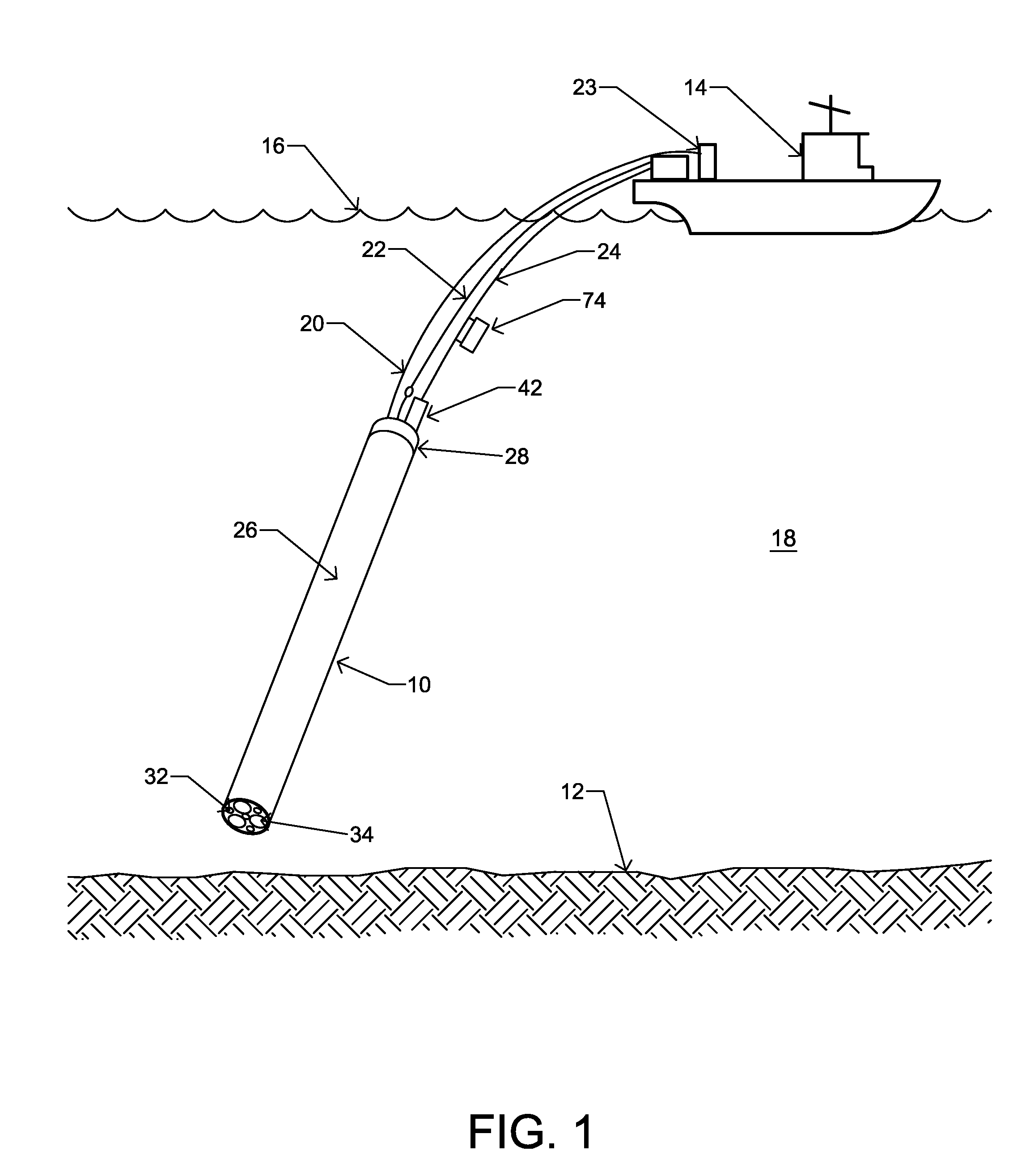
[0028]FIG. 1 depicts an exemplary suction corer device 10 in accordance with the present invention, which is useful for obtaining cores from a seabed 12. FIG. 1 depicts the corer device 10 having been deployed from a vessel 14 floating on the surface 16 of the sea 18. The corer device 10 is deployed from the vessel 14 by a mechanical tether 20. In addition, an air supply conduit 22 and a control line 24 extend from the vessel 14 to the corer device 10.

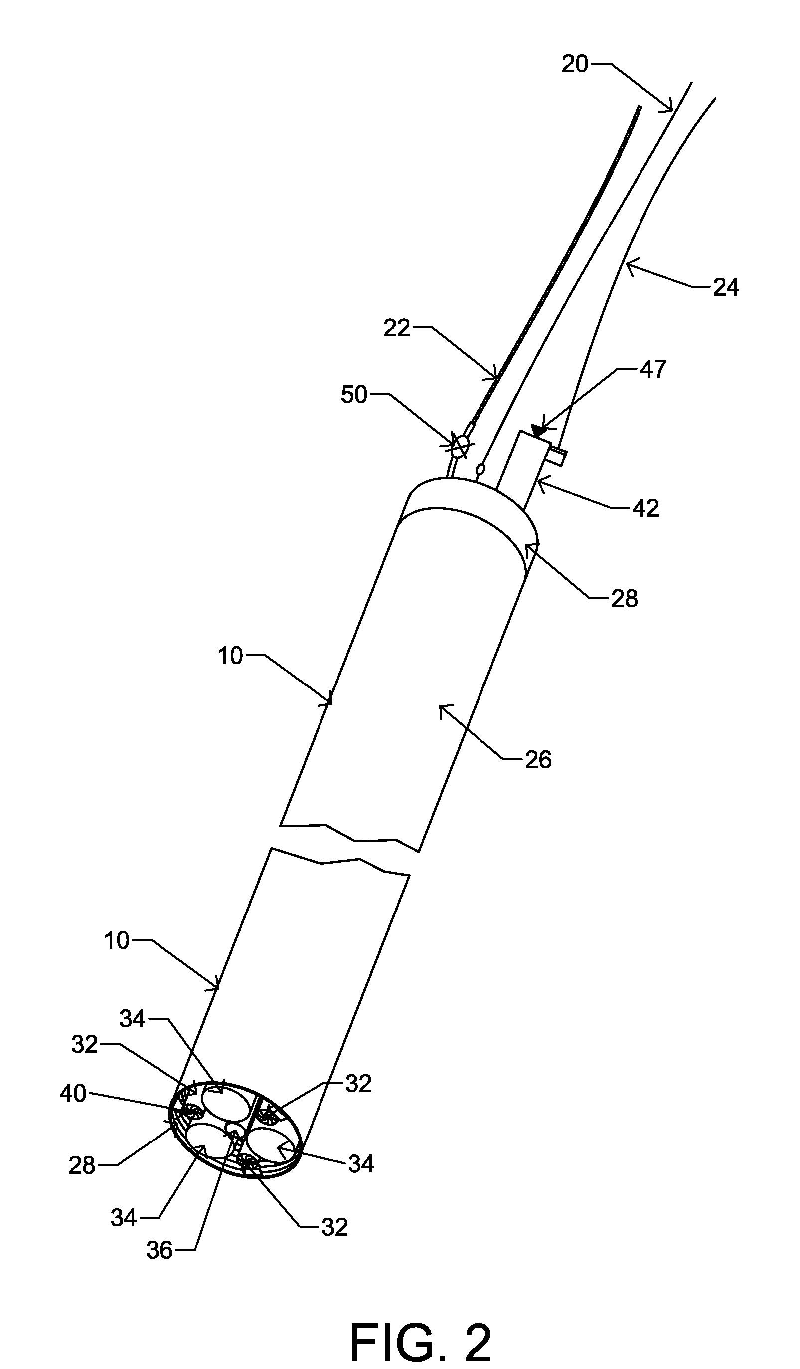
[0029]Construction of the exemplary corer device 10 is better understood with additional reference to FIGS. 2 and 3. The exemplary corer device 10 has an elongated, generally cylindrical outer casing 26 which defines a central axial chamber 28. A pressure housing 30 is secured to the upper end of the casing 26 by threading, welding, or another means known in the art. The central chamber 28 contains a set of hollow, generally cylindrical core barrels 32 and a set of hollow, generally cylindrical pressure barrels 34. In the depicted embo...


PUM


Abstract

Devices and methods for obtaining cores from a sea bed. A corer device includes one or more core barrels for retaining a cores and one or more pressure barrels. Fluid pressure within the pressure barrels is selectively varied to cause the corer device to be drawn into and released from the sea bed. The core barrels are provided with core catchers for retaining a core within.

Description

[0001]This application claims the benefit of U.S. Provisional Patent Application Ser. No. 60 / 881,927 filed Jan. 23, 2007.BACKGROUND OF THE INVENTION[0002]1. Field of the Invention[0003]The invention relates generally to devices and methods for obtaining cores from a sea bed.[0004]2. Description of the Related Art[0005]Current practices for seabed coring employ a coring device that is deployed from a surface vessel in a single coring run. The coring device relies on gravity to accelerate the coring device toward the sea floor and to provide the force with which the coring device penetrates the sea floor sediment. Alternatively, a drilling rig is deployed, either on a surface vessel or mounted on a remotely operated vehicle (ROV) which is landed on the sea bed. The drilling rig cores the sediment by rotary coring or by pushing a core barrel into the sea floor using the mass of the drill rig or drill string as a reaction mass against which to push the coring barrel. The core barrels ar...

Claims


Application Information

Patent Timeline
Patent Type & Authority Patents(United States)
IPC IPC(8): E21B7/26E21B7/04
CPCE21B25/18E21B7/124
Inventor FOLEY, ALAN
Owner FOLEY ALAN
Why Eureka
Try Eureka