
Scalable audio coding

a scalable, audio coding technology, applied in the field of audio signal coding, can solve the problems of reducing the noise signal, the available bit rate is too low, and the bandwidth limitation is effectively a reduction in the audio quality,

Inactive Publication Date: 2011-04-05
KONINK PHILIPS ELECTRONICS NV
View PDF24 Cites 12 Cited by
  • Summary
  • Abstract
  • Description
  • Claims
  • Application Information

AI Technical Summary

Benefits of technology

The present invention provides an audio encoder and decoder that allow for scalable encoding and decoding of audio signals. This means that modifications can be made to the encoded signal without introducing significant auditory artifacts. The encoder uses an excitation pattern to represent the audio signal, which is a spectral description of the human auditory system. The excitation pattern is computed based on the representation of the audio signal and a masking curve that describes the human hearing threshold. The masking curve helps to improve the efficiency of the encoding process by avoiding unnecessary bit allocation. The decoder then regenerates the audio signal by adding an appropriate signal to the first decoded signal part. This ensures that the perceived timbre of the reproduced signal is as close to the original signal as possible. The audio encoder and decoder can be selected from a variety of encoder and decoder types.

Problems solved by technology

Within low bit rate audio coding often the available bit rate is too low to model an entire spectrum of an audio signal with a deterministic type of encoder, such as a sinusoidal or a waveform encoder.
A disadvantage of this approach is that the necessary bandwidth limitation is effectively a reduction in audio quality.
However, regarding the second mentioned approach a problem is to determine how the noise signal should be generated.
The above described methods suffer from the disadvantage that already at the encoder side final decisions have to be made about the noise signal that is going to be generated at the decoder side.
As a consequence, it is not permitted that parameters or data for the deterministic part of the decoder are changed once the signal has been encoded.
If this is done, the consequence will be that, at the decoder side, the generated noise signal will not match the resulting signal from the deterministic decoder part and considerable audible artefacts can be the result.
In other words, noise coding according to the described principles is not scalable because it does not allow modifications to the deterministic signal after noise parameters have been estimated.

Method used


Image

  • Scalable audio coding
  • Scalable audio coding
  • Scalable audio coding

Examples


Embodiment Construction

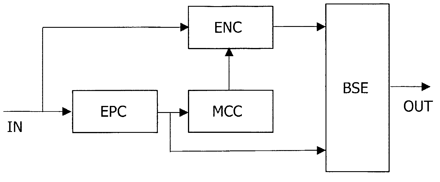
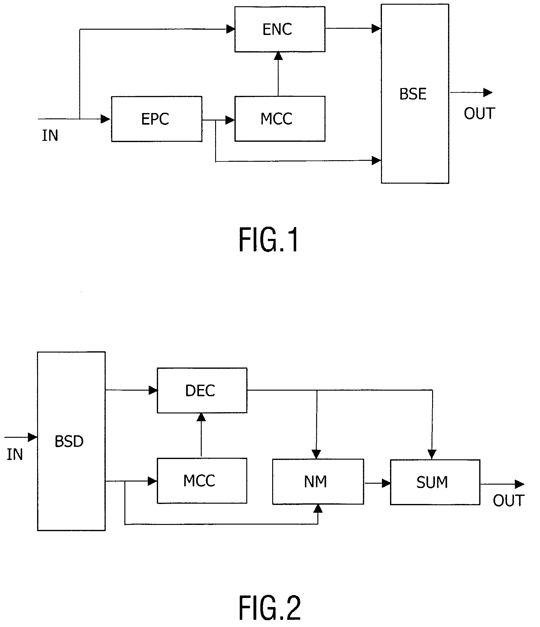
[0049]FIG. 1 shows a block diagram illustrating the principles of a preferred audio encoder with respect to signal flow. An audio input signal IN is applied to encoder means ENC. The encoder means ENC provides a first encoded signal part that is applied to a bit stream encoder BSE that provides the first encoded signal part to an output bit stream OUT from the audio encoder. Preferably, the encoder means comprises a deterministic type of encoder, such as a sinusoidal encoder or a transform encoder. In case of a sinusoidal encoder, the encoder determines which parts of the audio input signal IN to be modeled with sinusoids. In case of a transform encoder, the encoder means determines a set of transform coefficients to represent the audio input signal IN.

[0050]In the embodiment of FIG. 1 a spectral representation of the audio input signal IN is represented by its excitation pattern. The audio input signal IN is applied to excitation pattern computation means EPC adapted to compute an ...


PUM


Abstract

The invention relates to an audio encoder and decoder and methods for audio encoding and decoding. In a preferred encoder embodiment an audio signal is encoded by deterministic encoder means to form a first encoded signal part. A spectrum of the audio signal is determined and represented by an excitation pattern, i.e. spectral values corresponding to human auditory filters, as a second encoded signal part. A masking curve is also extracted based on the excitation pattern, thus improving encoding efficiency in terms of bit rate. In a preferred decoder the first encoded signal part is decoded by deterministic decoder means. A noise generator uses the decoded first signal part together with the second signal part, i.e. the excitation pattern for the original audio signal, to generate a noise signal. The noise signal is then added to the first decoded signal part to form an output audio signal. At the decoder side the masking curve is also extracted based on the second encoded signal part, i.e. the excitation pattern. The noise signal is generated so that the output audio signal exhibits an excitation pattern nearly identical to the original audio signal. Thus, a perceived high quality audio is obtained while the encoded signal is scalable since a possible deviation between encoding and decoding of the first signal part is compensated by the noise generator at the decoder side. In preferred embodiments the coding means comprises a sinusoidal coder.

Description

FIELD OF THE INVENTION[0001]The invention relates to the field of audio signal coding. Especially, the invention relates to efficient audio coding adapted for low bit rates. More specifically, the invention relates to scalable audio coding. The invention relates to an encoder, a decoder, methods for encoding and decoding, an encoded audio signal, storage and transmission media with data representing such encoded signal, and devices with an encoder and / or decoder.BACKGROUND OF THE INVENTION[0002]Within low bit rate audio coding often the available bit rate is too low to model an entire spectrum of an audio signal with a deterministic type of encoder, such as a sinusoidal or a waveform encoder. Two approaches have been used to overcome this problem.[0003]According to one approach bandwidth of the signal to be modeled is limited such that the available bit rate is sufficient to model the limited bandwidth with the deterministic encoder. A disadvantage of this approach is that the neces...

Claims


Application Information

Patent Timeline
Patent Type & Authority Patents(United States)
IPC IPC(8): G10L19/00G10L21/00G10L19/12G10L21/02G10L19/02G10L19/028G10L19/03G10L19/24G10L21/038
CPCG10L19/028G10L21/038G10L19/24G10L19/03G10L19/02G10L21/02
Inventor VAN DE PAR, STEVEN LEONARDUS JOSEPHUS DIMPHINA ELISABETHKOT, VALERY STEPHANOVICHVAN SCHIJNDEL, NICOLLE HANNEKE
Owner KONINK PHILIPS ELECTRONICS NV
Learn More