Compression system for internal combustion engine including a rotationally uncoupled exhaust gas turbine

a technology of exhaust gas turbine and compression system, which is applied in the direction of machines/engines, electric control, transportation and packaging, etc., can solve the problems of affecting the performance of the engine, limiting the operating state at which the compressor and the turbine can be operated, and the efficiency of the engine system may also be reduced, so as to achieve a rapid heating of the exhaust system, the effect of reducing the boost level

Active Publication Date: 2011-04-12
FORD GLOBAL TECH LLC
View PDF9 Cites 34 Cited by
  • Summary
  • Abstract
  • Description
  • Claims
  • Application Information

AI Technical Summary

Benefits of technology

[0002]The inventors of the present application have recognized that one disadvantage of the above turbocharger is that the compressor and turbine are rotationally coupled, which can limit the operating state at which the compressor and turbine can be operated. For example, compressor surge can be reduced by increasing an amount of exhaust flow bypassing the turbine, which can be achieved by increasing an opening of a wastegate arranged in a bypass passage of the turbine. By reducing the amount of exhaust energy that is extracted by the turbine, the speed and resulting boost pressure provided by the compressor can be reduced due to the rotational coupling, thereby reducing or eliminating compressor surge. However, by increasing the bypass flow of exhaust gases, the efficiency of the engine system may also be reduced since a greater amount of exhaust energy is transferred to ambient by way of the wastegate without being extracted by the turbine.
[0010]As such, the inventors have provided an approach that addresses this issue, as one example, by a method of operating an internal combustion engine including a first intake air compressor rotationally coupled with a first electric machine and an exhaust turbine rotationally coupled with a second electric machine, the method comprising: in response to a first operating state of the engine: increasing a flow of intake air through a bypass passage of the compressor relative to a flow of intake air through the compressor by opening a compressor bypass valve; and generating a first amount electrical energy with the second electric machine by extracting exhaust gas energy flowing from the engine via the turbine; and in response to a second operating state of the engine: decreasing the flow of intake air through the bypass passage of the compressor relative to the flow of intake air through the compressor by closing the compressor bypass valve; supplying electrical energy to the first electric machine to increase the rotational speed of the compressor; generating a second amount of electrical energy greater than the first amount with the second electric machine by extracting exhaust gas energy from the engine via the turbine; and adjusting the speed of the turbine relative to the compressor to vary the second amount of electrical energy generated by the second electric machine. In this way, engine efficiency may be increased during conditions where a lower amount of boost is requested or where the compressor is inactive.

Problems solved by technology

The inventors of the present application have recognized that one disadvantage of the above turbocharger is that the compressor and turbine are rotationally coupled, which can limit the operating state at which the compressor and turbine can be operated.
However, by increasing the bypass flow of exhaust gases, the efficiency of the engine system may also be reduced since a greater amount of exhaust energy is transferred to ambient by way of the wastegate without being extracted by the turbine.
If boost is simply increased by adjusting the compressor, the amount and / or concentration of residuals retained by the cylinders may also change, thereby potentially impacting the performance of the engine depending on the combustion mode presently utilized.
For example, during warm-up of the engine, if the turbine is operated to extract exhaust gas energy from the exhaust stream, then the exhaust treatment devices may take longer to reach their prescribed operating temperature.
However, the compressor can serve as an obstruction to the intake system during conditions where additional boost is not prescribed for the given engine operating state.

Method used


Image

  • Compression system for internal combustion engine including a rotationally uncoupled exhaust gas turbine
  • Compression system for internal combustion engine including a rotationally uncoupled exhaust gas turbine
  • Compression system for internal combustion engine including a rotationally uncoupled exhaust gas turbine

Examples


Embodiment Construction

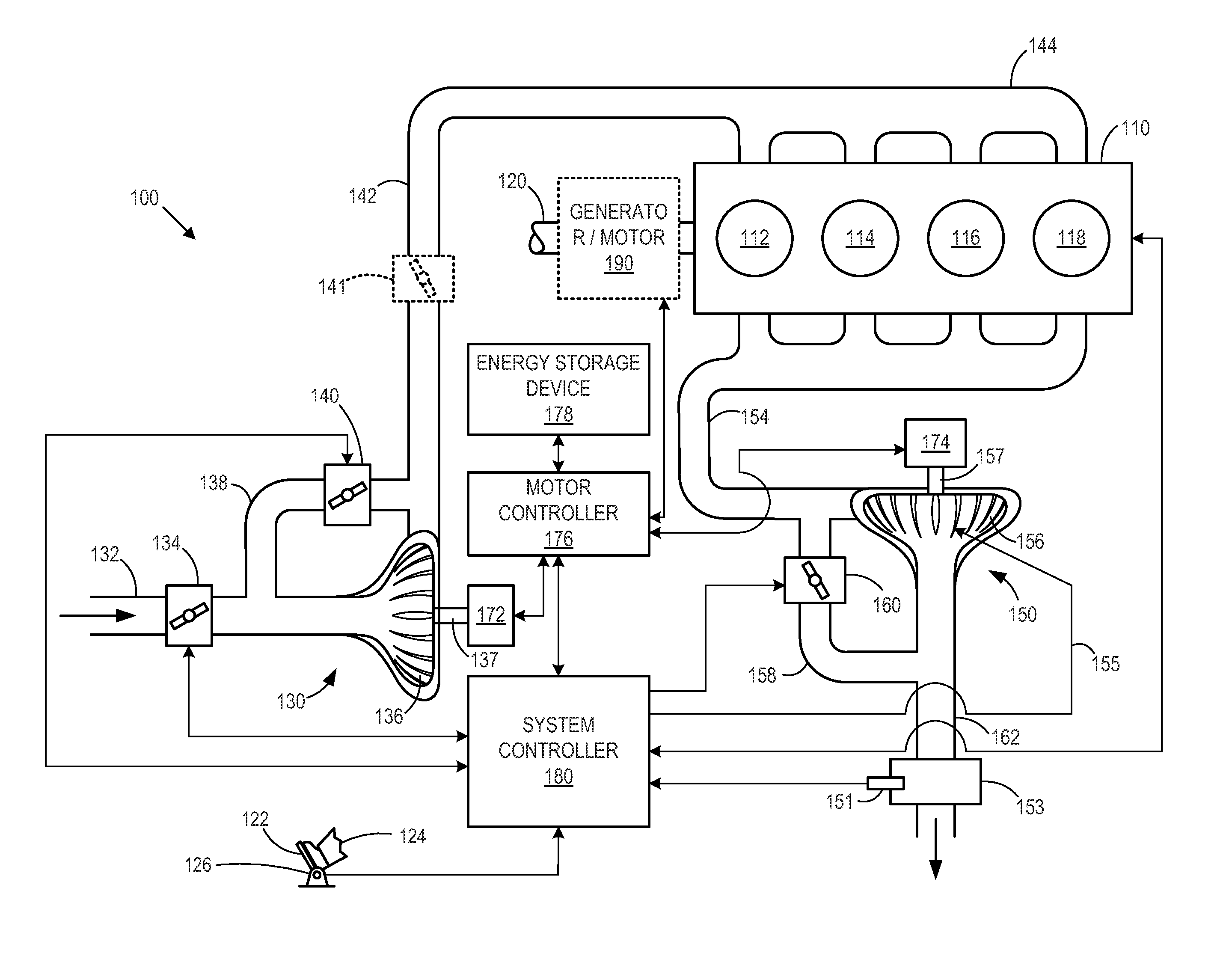
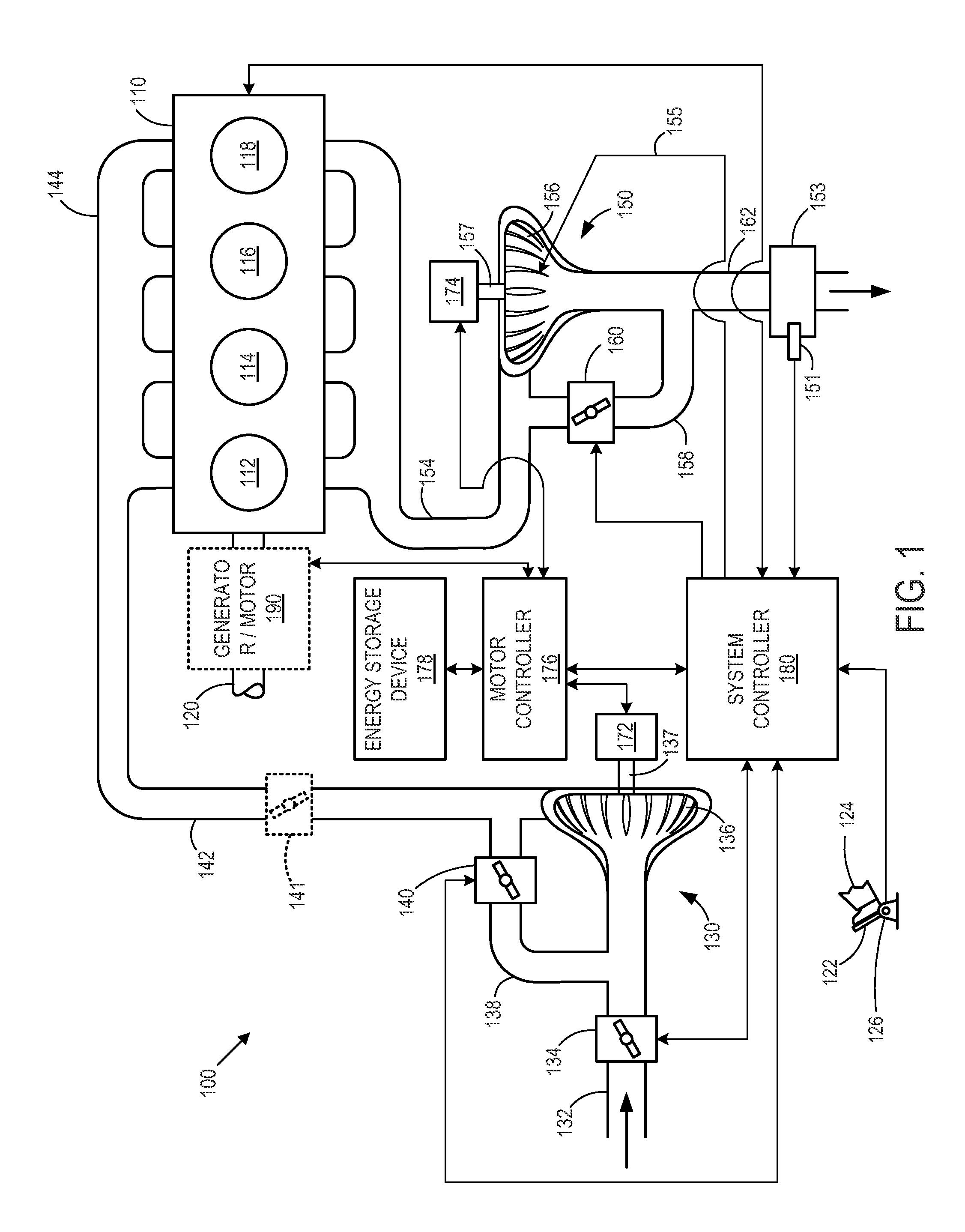
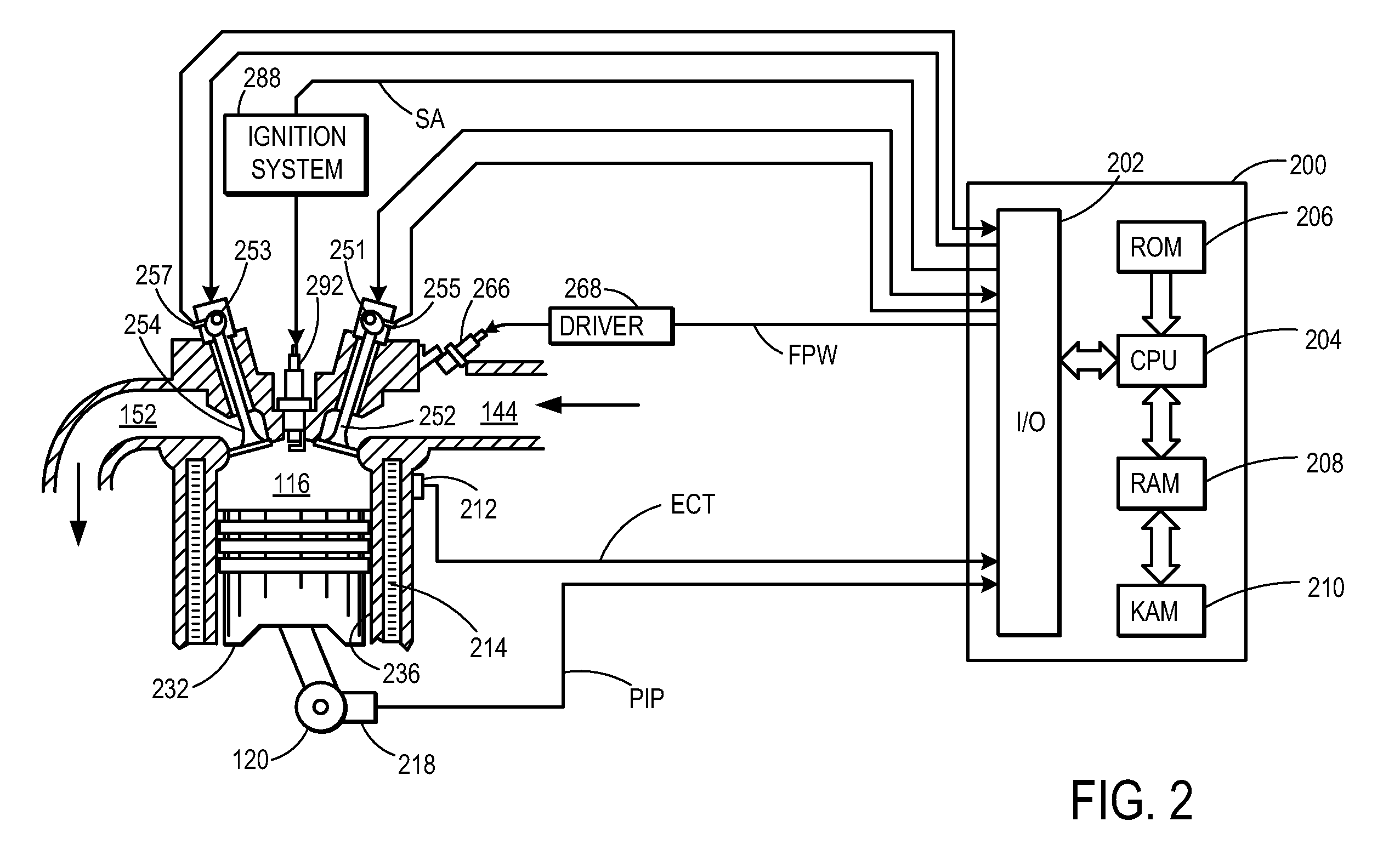
[0020]FIG. 1 shows a schematic depiction of an example vehicle propulsion system 100. Propulsion system 100 includes an internal combustion engine 110 having a plurality of combustion chambers or cylinders indicated at 112, 114, 116, and 118. A more detailed description an example engine cylinder is provided with reference to FIG. 2. While this particular example shows engine 110 including four cylinders, it should be appreciated that in other examples engine 110 may include any suitable number of cylinders.

[0021]Engine 110 can receive intake air via an intake system indicated generally at 130 and can exhaust combustion gases via an exhaust system indicated generally at 150. Intake system 130 can include an air intake passage 132 that includes a throttle 134. The position of throttle 134 can be adjusted by controller 180 to vary the flow rate of intake air provided to engine 110 as well as the pressure within the intake system downstream of the throttle. Intake passage 132 can commu...


PUM


Abstract

As one example, a vehicle propulsion system is provided. The system includes: an with an intake air compressor and an exhaust gas turbine. Further, a control is provided to operate the compressor at a different speed than the turbine, at least under an operating condition, and to adjust an amount of opening overlap between engine valves in response to a rotational speed of the compressor.

Description

BACKGROUND AND SUMMARY[0001]Internal combustion engines can utilize turbochargers or superchargers to obtain increased intake air pressure to enable increased engine performance. Turbochargers typically include an intake air compressor rotationally coupled with an exhaust gas turbine, where the turbine provides thrust to the compressor by extracting energy from the exhaust flow. Some of turbochargers may include a motor to assist the compressor develop sufficient thrust when the turbine is unable to extract enough energy from the exhaust flow or where the exhaust flow has insufficient energy to power the compressor.[0002]The inventors of the present application have recognized that one disadvantage of the above turbocharger is that the compressor and turbine are rotationally coupled, which can limit the operating state at which the compressor and turbine can be operated. For example, compressor surge can be reduced by increasing an amount of exhaust flow bypassing the turbine, which...

Claims


Application Information

Patent Timeline
Patent Type & Authority Patents(United States)
IPC IPC(8): B60W10/06B60W10/08
CPCF02B33/40F02B39/16F02B39/10F02D41/0007F02D41/3035F02D41/3058Y02T10/12
Inventor RUSSELL, JOHN D.SURNILLA, GOPICHANDRA
Owner FORD GLOBAL TECH LLC
Why Eureka
Try Eureka