Turbine blade with blade tip cooling passages

Inactive Publication Date: 2011-04-12
FLORIDA TURBINE TECH
View PDF18 Cites 70 Cited by
  • Summary
  • Abstract
  • Description
  • Claims
  • Application Information

AI Technical Summary

Benefits of technology

[0014]This problem associated with turbine airfoil tip edge cooling and sealing can be eliminated by the use of the discrete curved cooling channels of the present invention in to the squealer tip of the turbine blade. Discrete curved cooling channels are formed in the tip rails of the blade on the pressure side and the suction side external walls, through the tip walls and onto the tip crown

Problems solved by technology

The blade tip gap leakage not only reduces the efficiency of the turbine by not impacting all of the gas flow onto the turbine rotor blades, but can cause thermal damage to the blade tips and result in shortened life for the blades.
A high leakage flow will induce a high heat load onto the blade tip section.
High heat loads on the blade tip can cause erosion or other thermal damage to the tip that will decrease part life or decrease engine performance.
Cooling of the squealer tip rail by means of discharge row of film cooling holes along the b

Method used


Image

  • Turbine blade with blade tip cooling passages
  • Turbine blade with blade tip cooling passages
  • Turbine blade with blade tip cooling passages

Examples


Embodiment Construction

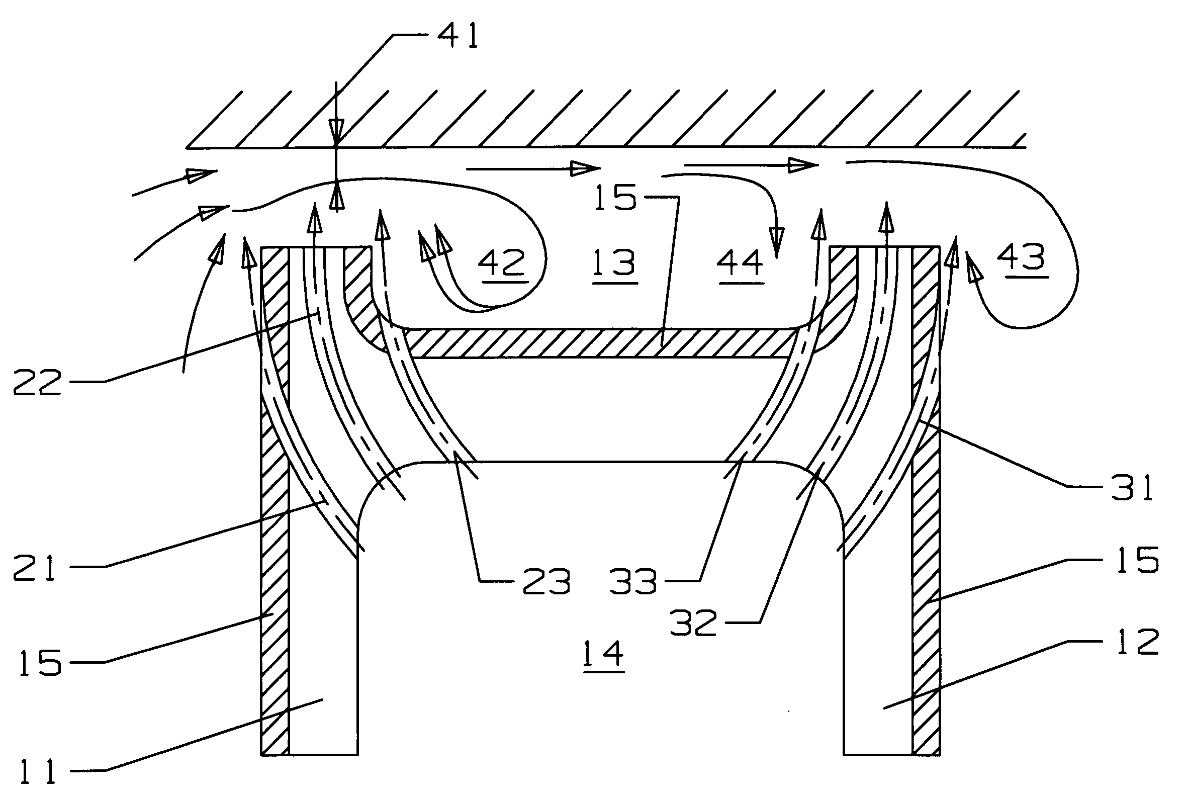
[0021]A turbine rotor blade used in an industrial gas turbine engine in which the turbine blade includes a squealer tip to limit hot gas flow leakage and to cool the blade tip. The blade tip of the present invention includes a number of curved blade tip cooling passages or channels formed within the walls and the tip rail and the pocket floor to provide improved cooling effectiveness over the cited prior art references and to form a vena contractor effective flow area on the pressure side and a hot gas recirculation on the suction side to reduce the hot gas flow leakage across the gap.

[0022]FIG. 5 shows a cross section view of the blade tip with the cooling passages of the present invention. the blade includes a pressure side wall 11 with a TBC 15 applied up to the tip rail, and a suction side wall 12 also with a TBC 15 applied up to the tip rail. A squealer pocket 13 is formed between the pressure side tip rail and the suction side tip rail. A cooling supply passage or cavity 14 is...


PUM


Abstract

A turbine blade for use in an industrial gas turbine engine, the blade having a squealer pocket with a plurality of discrete curved cooling channels to cool the blade tip and to reduce the hot gas flow leakage across the tip. The curved cooling channels include a side wall cooling channel, a tip rail crown cooling channel and an inner tip rail wall cooling channel all discharging cooling air from a cooling supply channel within the airfoil. Both the pressure side and suction side tip rails include this arrangement of cooling channels.

Description

BACKGROUND OF THE INVENTION[0001]1. Field of the Invention[0002]The present invention relates generally to a turbine rotor blade, and more specifically to a turbine rotor blade with a squealer tip.[0003]Description of the Related Art including information disclosed under 37 CFR 1.97 and 1.98[0004]In a gas turbine engine, especially an industrial gas turbine engine, the turbine section includes a plurality of stages of turbine rotor blades with blade tips that from a gap with an outer shroud of the engine in which the hot gas flow passing through the turbine can leak past the blade tips. The blade tip gap leakage not only reduces the efficiency of the turbine by not impacting all of the gas flow onto the turbine rotor blades, but can cause thermal damage to the blade tips and result in shortened life for the blades.[0005]In a high temperature turbine blade tip section, the heat load is a function of the blade tip leakage flow. A high leakage flow will induce a high heat load onto the...

Claims


Application Information

Patent Timeline
IPC IPC(8): F01D5/08
CPCF01D5/187F01D5/20F05D2260/20F05D2250/71F01D5/186
Inventor LIANG, GEORGE
Owner FLORIDA TURBINE TECH
Why Eureka
Try Eureka