
Inorganic nanowires

a nanowire and organic technology, applied in the field of organic nanowires, can solve the problems of affecting the production efficiency of nanowires, affecting the quality of nanowires, and affecting the quality of nanowires, and achieve good monodispersity

Inactive Publication Date: 2011-04-12
BOARD OF RGT THE UNIV OF TEXAS SYST +1
View PDF30 Cites 6 Cited by
  • Summary
  • Abstract
  • Description
  • Claims
  • Application Information

AI Technical Summary

Benefits of technology

The present invention provides a method for producing inorganic nanowires with an organic scaffold that is removed during the production process. The inorganic nanowires consist of fused inorganic nanoparticles and can be used in various applications such as electronics, sensors, and field effect transistors. The invention also provides a composition of inorganic nanowires and a process for producing them using an elongated organic scaffold. The inorganic nanowires have a high energy phase and can be made monodisperse in length or width. The invention also provides an inorganic nanowire with fused inorganic nanoparticles.

Problems solved by technology

Although each method developed for the production of nanowires has had some basic success in achieving high quality materials, methods to date have not yielded monodisperse, crystalline nanowires of radically different compositions.
In general, prior methods for nanowire production can be erratic, synthetically cumbersome, and are not universal.
It describes a VLS process that requires use of lasers and high temperatures and produces a nanowire having a nanoparticle at the end which may not be desirable.

Method used


Image

  • Inorganic nanowires
  • Inorganic nanowires
  • Inorganic nanowires

Examples


working examples

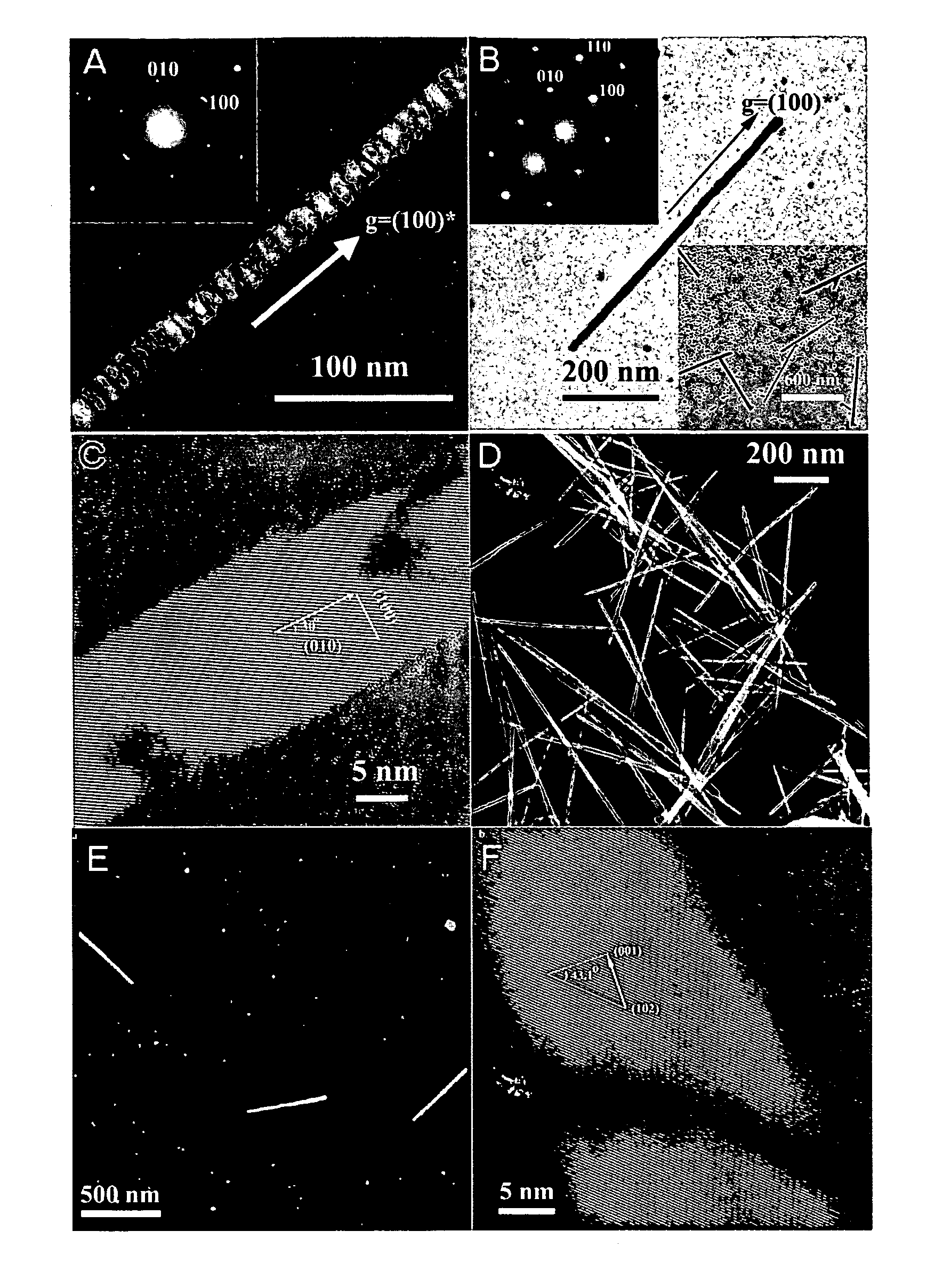
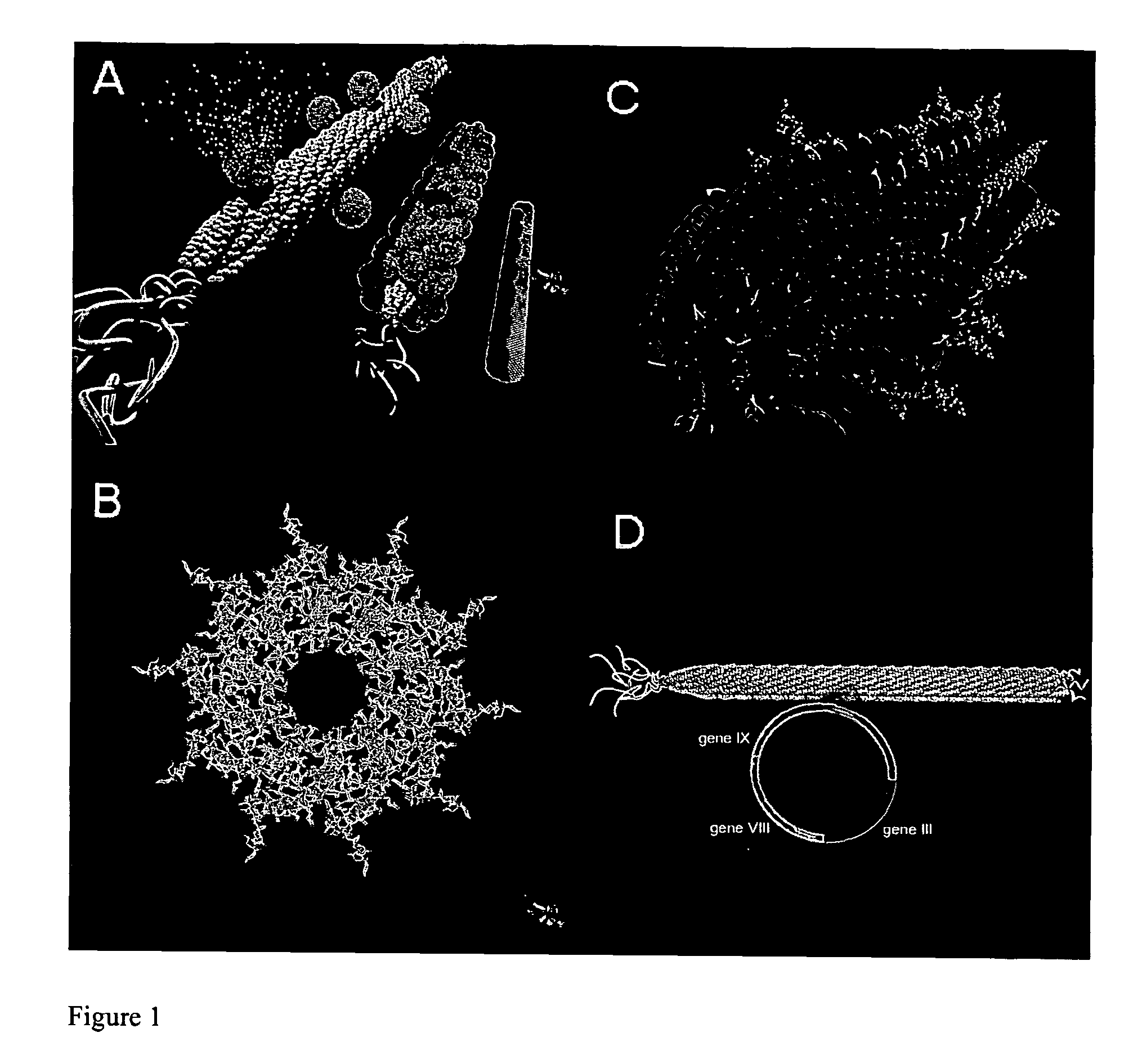
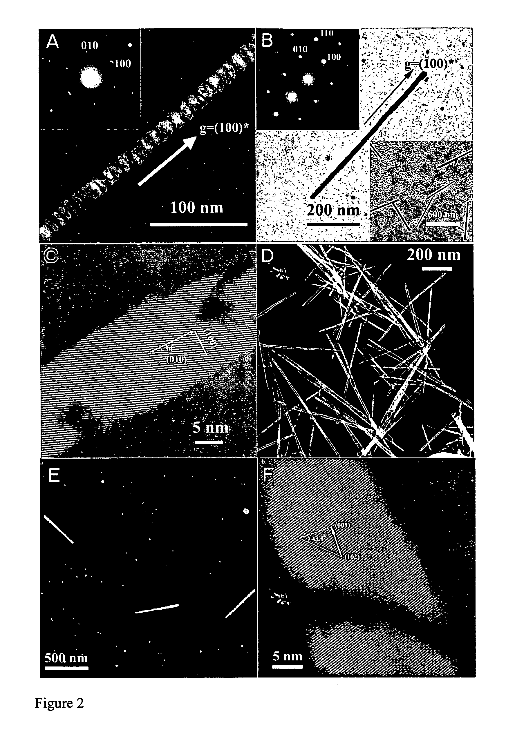
[0088]The present invention is further characterized by the following non-limiting working examples including FIGS. 2 and 3 and description and discussion thereof. One skilled in the art can use as guidance FIGS. 1-3 in the practice of the present invention which provide an introduction to the working examples.

[0089]FIG. 1

[0090]FIG. 1A illustrates the nanowire synthesis scheme or the nucleation, ordering and annealing of virus-particle assemblies. FIG. 1B shows the symmetry of the virus. The symmetry allows for ordering of the nucleated particles along the x,y, and z directions fulfilling requirements for aggregation based annealing. FIG. 1C shows the highly ordered nature of the M13 bacteriophage. The highly ordered nature of the self assembled M13 bacteriophage promotes the preferred orientation seen in nucleated particles through the rigidity and packing of the expressed peptides, which is visualized at 20% incorporation. FIG. 1D shows the construct of the M13 bacteriophage virus...


PUM

PropertyMeasurementUnit
widthaaaaaaaaaa
lengthaaaaaaaaaa
aspect ratioaaaaaaaaaa

Abstract

An inorganic nanowire having an organic scaffold substantially removed from the inorganic nanowire, the inorganic nanowire consisting essentially of fused inorganic nanoparticles substantially free of the organic scaffold, and methods of making same. For example, a virus-based scaffold for the synthesis of single crystal ZnS, CdS and free-standing L10 CoPt and FePt nanowires can be used, with the means of modifying substrate specificity through standard biological methods. Peptides can be selected through an evolutionary screening process that exhibit control of composition, size, and phase during nanoparticle nucleation have been expressed on the highly ordered filamentous capsid of the M13 bacteriophage. The incorporation of specific, nucleating peptides into the generic scaffold of the M13 coat structure can provide a viable template for the directed synthesis of a variety of materials including semiconducting and magnetic materials. Removal of the viral template via annealing can promote oriented aggregation-based crystal growth, forming individual crystalline nanowires. The unique ability to interchange substrate specific peptides into the linear self-assembled filamentous construct of the M13 virus introduces a material tunability not seen in previous synthetic routes. Therefore, this system provides a genetic tool kit for growing and organizing nanowires from various materials including semiconducting and magnetic materials.

Description

[0001]This invention was made with government supported awarded by the Army Research Office under Grant Number DAAD19-03-1-0088. The government has certain rights in the invention.[0002]This application claims benefit under 35 U.S.C. §119(e) to provisional application No. 60 / 534,102 filed Jan. 5, 2004 by Belcher et al., which is hereby incorporated by reference in its entirety.INTRODUCTION[0003]The reliance of a wide variety of technologies on developing scalable and economic methods for the fabrication of one-dimensional materials, including nanowires and nanotubes, has spurred intense and rapid progress in the area of materials synthesis. For example, one-dimensional materials have been enthusiastically pursued for their applications in the study of, for example, electrical transport (1), optical phenomena (2), and as functional units in nanocircuitry (3). Pursuit of “bottom up” methods for the synthesis of semiconducting, metallic and magnetic nanowires has yielded a variety of s...

Claims


Application Information

Patent Timeline
Patent Type & Authority Patents(United States)
IPC IPC(8): D02G3/00C04B35/64H01L29/06H01L29/22H01L29/745H05B6/00
CPCB82Y30/00C01G9/08C04B35/62272H01L29/0665H01L29/0669H01L29/0673H01L29/22B82Y10/00H01B1/10H01F1/01H01B1/06C01B19/007Y10T428/298C01P2004/04C01P2004/16C04B2235/3284C04B2235/446H01F1/068Y10T428/2927Y10T428/2913Y10T428/249924
Inventor BELCHER, ANGELA M.MAO, CHUANBINSOLIS, DANIEL J.
Owner BOARD OF RGT THE UNIV OF TEXAS SYST
Learn More