Electrically operated hydraulic pump

a hydraulic pump and electric motor technology, applied in the direction of electronic commutators, motor/generator/converter stoppers, dynamo-electric converter control, etc., can solve the problems of insufficient control of the rotational position of the motor, the reduction of the detection precision of the rotational position of the rotor,

Inactive Publication Date: 2011-04-19
AISIN SEIKI KK
View PDF5 Cites 32 Cited by
  • Summary
  • Abstract
  • Description
  • Claims
  • Application Information

AI Technical Summary

Problems solved by technology

However, when the rotation speed of the rotor is not high, the detection precision of the rotational position of the rotor may be decreased.
Consequently, the rotation of the motor may not be controlled adequately.

Method used


Image

  • Electrically operated hydraulic pump
  • Electrically operated hydraulic pump
  • Electrically operated hydraulic pump

Examples


Embodiment Construction

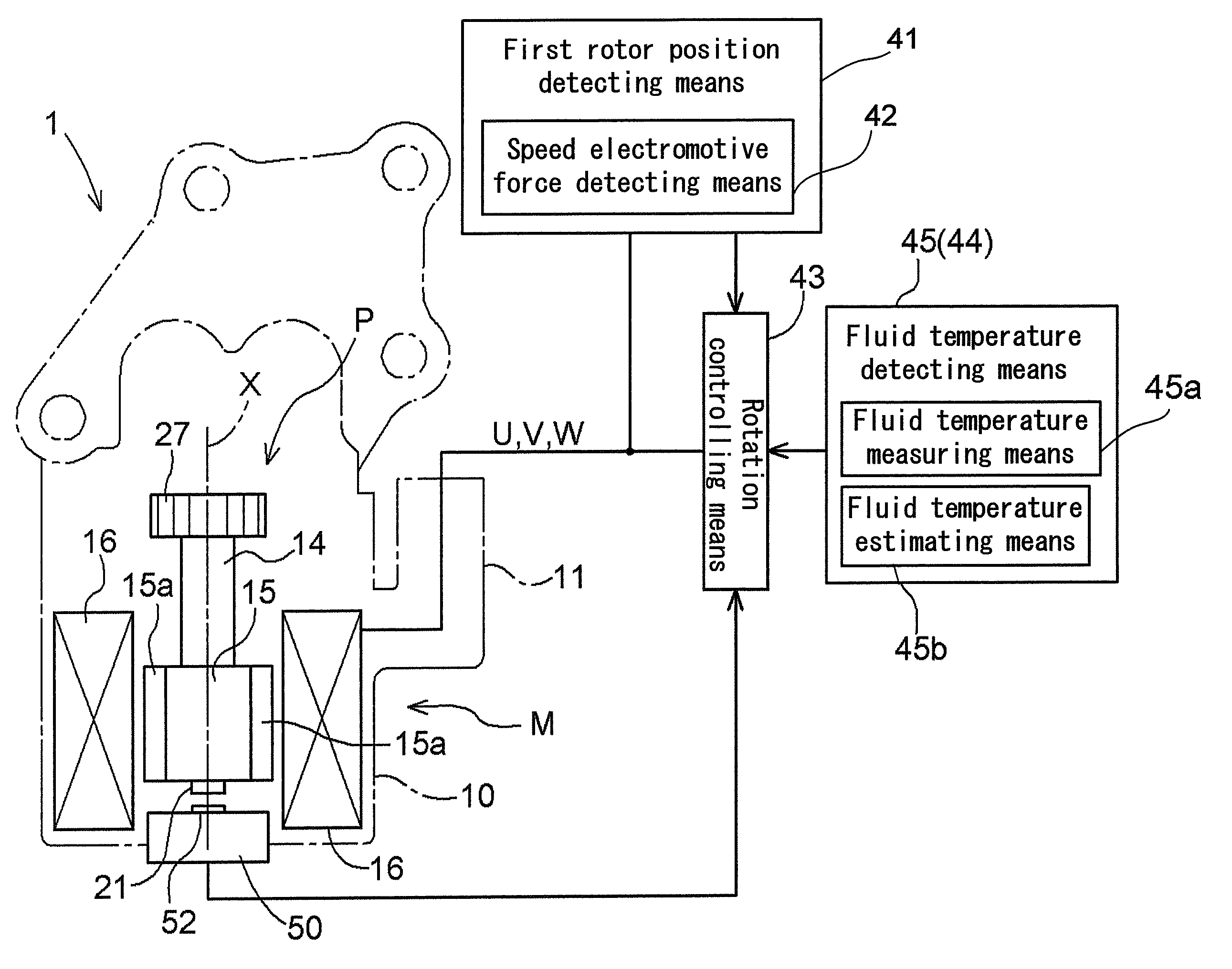
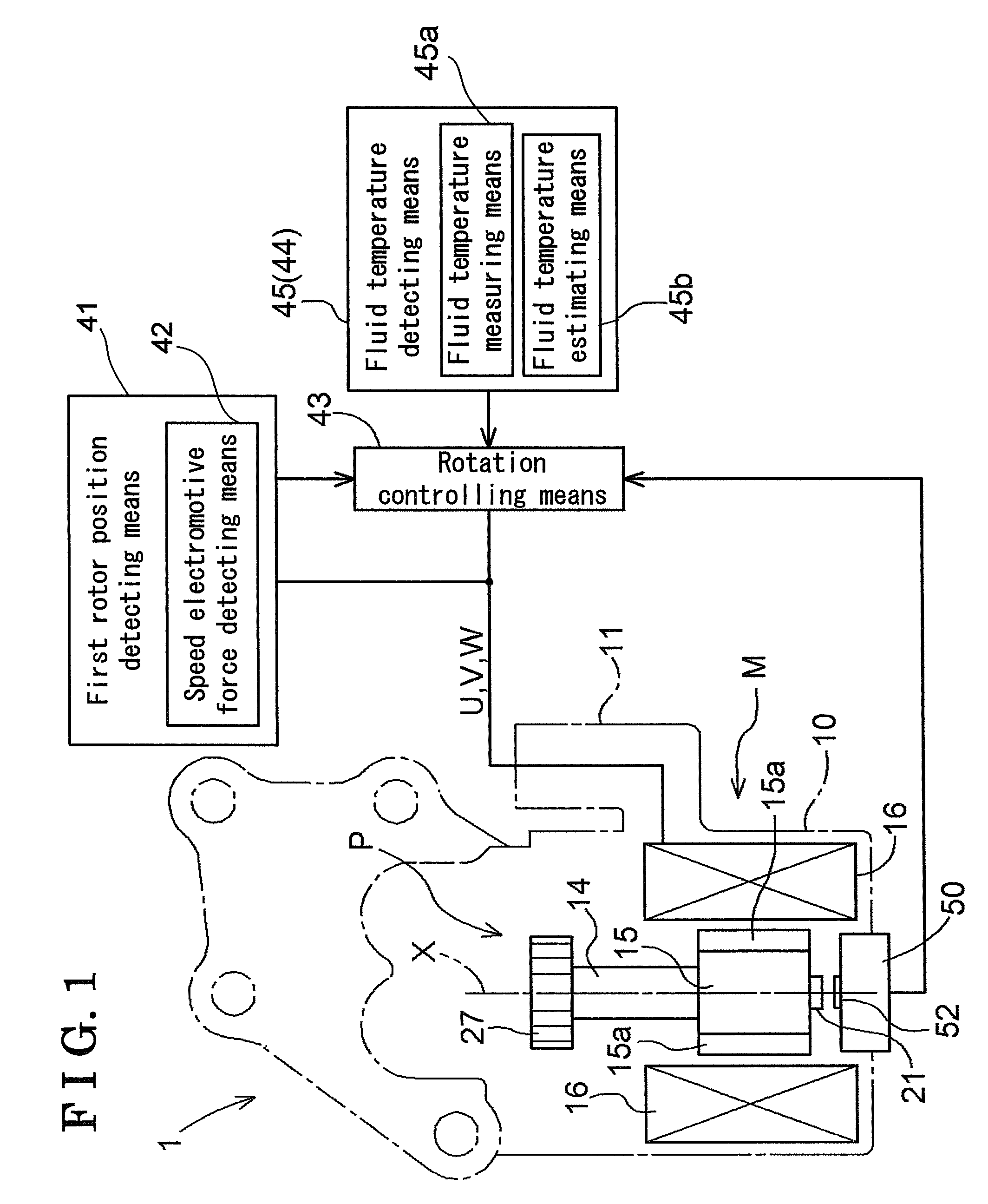
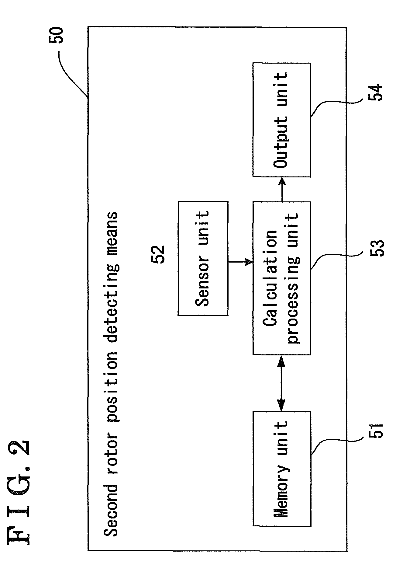
[0014]An embodiment of the electrically operated hydraulic pump according to the present invention will be described hereinafter with reference to attached FIGS. 1 through 4. FIG. 1 is a longitudinal sectional view schematically illustrating an entire structure of the electrically operated hydraulic pump. FIG. 2 is a functional block diagram illustrating a second rotor position detecting means of the electrically operated hydraulic pump illustrated in FIG. 1. FIG. 3 is a longitudinal sectional view illustrating in detail the electrically operated hydraulic pump. FIG. 4 is a top view of the motor portion of the electrically operated hydraulic pump. As best shown in FIGS. 1 and 3, an electrically operated hydraulic pump 1 includes a motor portion M and a pump portion P. The motor portion M drives a rotating shaft 14 to rotate, by means of electric power supplied via a connecting portion 11. The pump portion P is provided at one end of the rotating shaft 14, and absorbs and exhausts fl...


PUM


Abstract

An electrically operated hydraulic pump having a pump portion and a motor portion includes rotation controlling means controlling rotation of a rotor, first rotor position detecting means detecting rotational position of the rotor on the basis of speed electromotive force induced by exciting coils, second rotor position detecting means detecting the rotational position of the rotor on the basis of magnetic field of a magnet provided at the motor portion, and motor operating condition detecting means detecting operating condition of the motor portion. The rotation controlling means switches a first rotation controlling based on the rotational position of the rotor detected by the first rotor position detecting means, and a second rotation controlling based on the rotational position of the rotor detected by the second rotor position detecting means, on the basis of a result detected by the motor operating condition detecting means.

Description

CROSS REFERENCE TO RELATED APPLICATIONS[0001]This application is based on and claims priority under 35 U.S.C. §119 to Japanese Patent Application 2006-262669, filed on Sep. 27, 2006, the entire content of which is incorporated herein by reference.FIELD OF THE INVENTION[0002]The present invention relates to an electrically operated hydraulic pump which includes a pump portion and a motor portion including a brushless DC motor, and which detects a rotational position of the rotor included in the motor, on the basis of speed electromotive force induced by exciting coils of the motor portion.BACKGROUND[0003]An electrically operated hydraulic pump is used for supplying operating oil as fluid to a clutch of an automatic transmission mounted on a vehicle such as an automobile, or for supplying cooling oil as fluid to an electric motor mounted on a hybrid type vehicle, and so on. A mechanical hydraulic pump, an electrically operated hydraulic pump, and so on can be employed as a pump mounte...

Claims


Application Information

Patent Timeline
Patent Type & Authority Patents(United States)
IPC IPC(8): F04B49/10H02P6/04H02P6/18F04B49/06F04C15/00H02K7/14H02P6/06H02P6/08H02P6/16H02P6/182
CPCF04C2/102F04C11/008F04C14/08F04C2270/19F04C2270/052F04C2270/11
Inventor SUZUKI, SHIGEMITSUYAMAMOTO, SHIGEHARUTOMA, NAOTO
Owner AISIN SEIKI KK
Why Eureka
Try Eureka