
Apparatus and method for reducing cardiac valve regurgitation

a technology of cardiac valve and appendix, which is applied in the field of appendix, can solve the problems of time-consuming procedures, like heart valve replacement, and achieve the effect of reducing the regurgitation of blood flow

Active Publication Date: 2011-04-19
THE CLEVELAND CLINIC FOUND
View PDF30 Cites 120 Cited by
  • Summary
  • Abstract
  • Description
  • Claims
  • Application Information

AI Technical Summary

Benefits of technology

[0007]In another aspect of the present invention, an apparatus for modifying the annulus of a cardiac valve to reduce regurgitation of blood flow through the cardiac valve comprises a first annuloplasty ring having a first diameter and being disposed about a first aspect of the annulus of the cardiac valve, and a flexible body comprising first and second oppositely disposed strut members having proximal and distal end portions. The flexible body additionally includes a cinching mechanism for adjusting the flexible body from a first relaxed configuration to a second tensioned configuration. The cinching mechanism is operatively connected to the distal end portion of the strut members. The cinching mechanism comprises a resistance member operatively coupled to the distal end portion of the strut members, and a harness member operatively coupled to a pull wire extending between the strut members. The flexible body is disposed in a delivery catheter that is insertable into the first annuloplasty ring. The delivery catheter comprises proximal and distal end portions and an opening at the distal portion for extending the harness member therethrough. The flexible body is adaptable to obtain the second tensioned configuration and to cause the first annuloplasty ring to obtain a second smaller diameter so that the annulus of the cardiac valve is modified and regurgitation of blood flow through the cardiac valve is reduced.

Problems solved by technology

This procedure, like heart valve replacement, is time-consuming.

Method used


Image

  • Apparatus and method for reducing cardiac valve regurgitation
  • Apparatus and method for reducing cardiac valve regurgitation
  • Apparatus and method for reducing cardiac valve regurgitation

Examples


Embodiment Construction

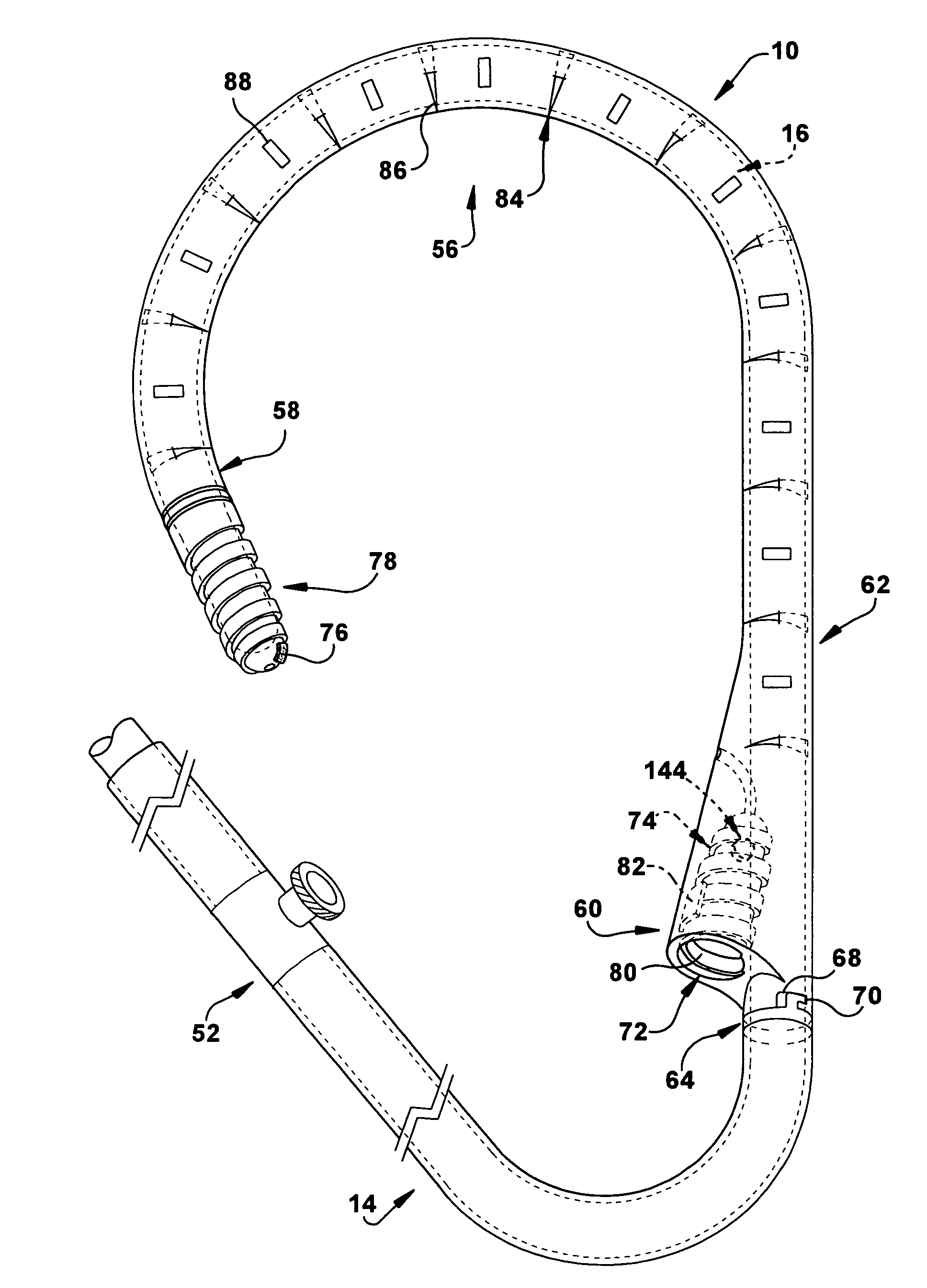
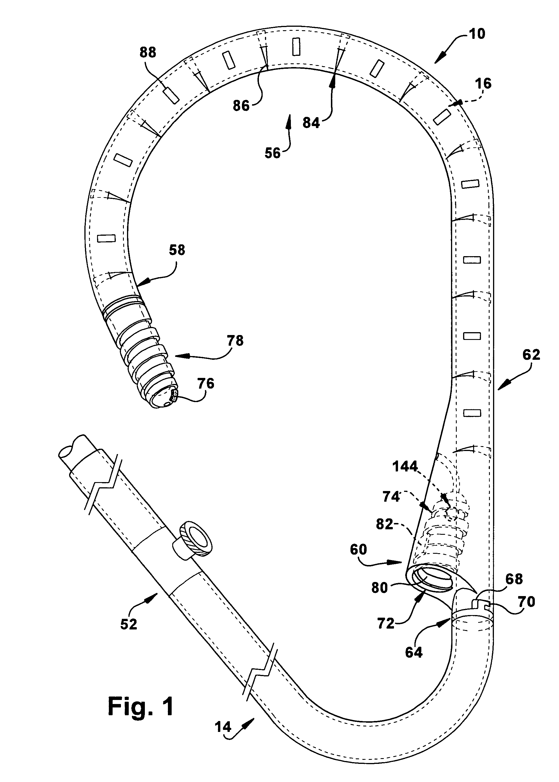
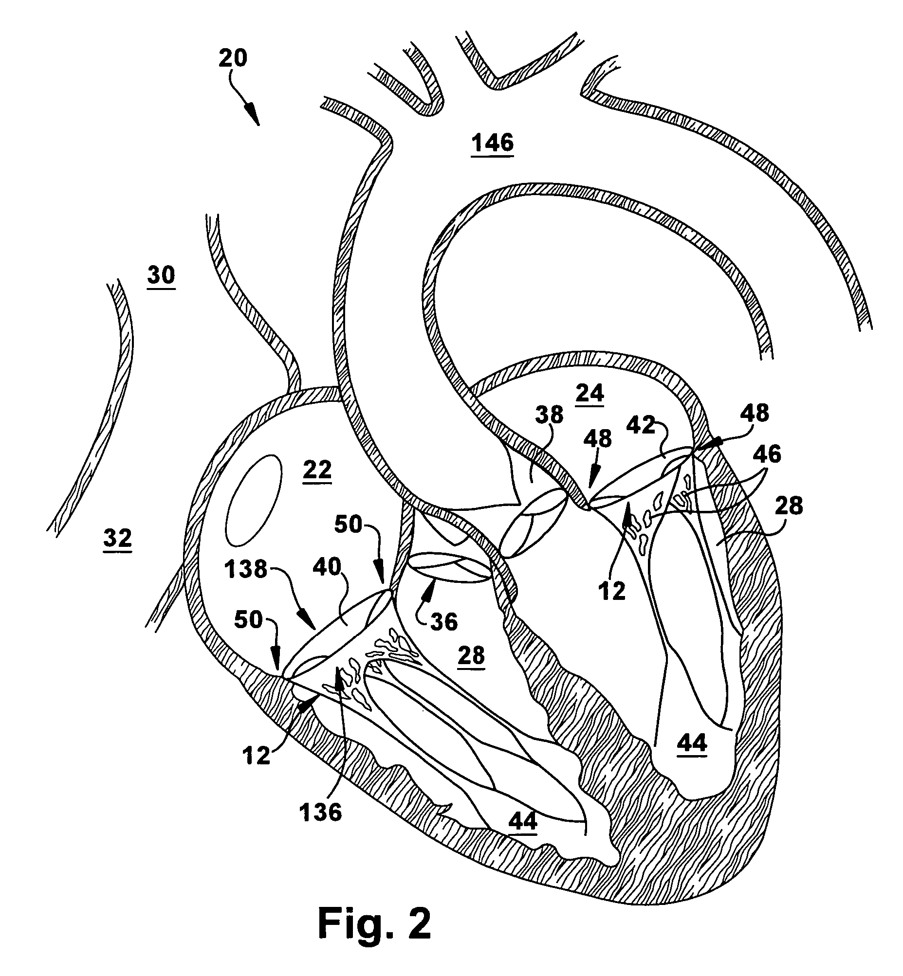
[0051]The present invention relates generally to an apparatus and method for treating cardiac valve insufficiencies, and more particularly to an apparatus and method for reducing or preventing regurgitation of blood flow through a cardiac valve. As representative of the present invention, FIG. 1 illustrates an apparatus 10 for modifying a cardiac valve 12 (FIG. 2) comprising a first annuloplasty ring 14 (FIG. 1) and an elongate flexible body 16. The elongate flexible body 16 is insertable into the first annuloplasty ring 14 and may be adjusted so that the annulus 18 of the cardiac valve 12 (FIG. 2) is modified and regurgitation of blood flow through the cardiac valve is reduced or eliminated.

[0052]FIG. 2 shows a human heart 20. The human heart 20 contains four chambers: the right and left atria 22 and 24 and the right and left ventricles 26 and 28. The thin-walled right atrium 22 receives deoxygenated blood from the superior vena cava 30, the inferior vena cava 32, and from the coro...


PUM


Abstract

An apparatus for modifying the annulus of a cardiac valve to reduce regurgitation of blood flow through the cardiac valve includes a first annuloplasty ring having a first diameter and being disposed about a first aspect of the annulus of the cardiac valve. The apparatus also includes an elongate flexible body having proximal and distal end portions and being insertable into the first annuloplasty ring. The elongate flexible body has an adjustable mechanism for selectively adjusting the elongate flexible body from a first relaxed configuration to a second tensioned configuration. The first annuloplasty ring is adaptable to obtain a second smaller diameter and to cause the annulus of the cardiac valve to be modified and reduce regurgitation of blood flow through the cardiac valve when the elongate flexible body obtains the second tensioned configuration.

Description

RELATED APPLICATIONS[0001]This application is a continuation-in-part of U.S. patent application Ser. No. 11 / 486,584, filed Jul. 14, 2006 now abandoned, which claims priority from U.S. Provisional Patent Application Ser. No. 60 / 699,730, filed Jul. 15, 2005. The subject matter of the aforementioned applications is incorporated herein by reference in their entireties.TECHNICAL FIELD[0002]The present invention relates generally to an apparatus and method for treating cardiac valve insufficiencies, and more particularly to an apparatus and method for reducing or preventing regurgitation of blood flow through a cardiac valve.BACKGROUND OF THE INVENTION[0003]Mitral and tricuspid valve replacement and repair are traditionally performed with suture techniques. During valve replacement, sutures are spaced around the annulus (the point where the valve leaflet attaches to the heart) and then the sutures are attached to a prosthetic valve. The valve is lowered into position and when the sutures ...

Claims


Application Information

Patent Timeline
Patent Type & Authority Patents(United States)
IPC IPC(8): A61F2/24
CPCA61F2/2445A61F2/2466A61F2250/0004A61F2250/0001A61F2210/009
Inventor NAVIA, JOSE LUISNAVIA, JOSE ANTONIOKASSAB, GHASSAN
Owner THE CLEVELAND CLINIC FOUND
Learn More