Apparatus for outputting complementary signals using bootstrapping technology

a technology of complementary signals and bootstrapping circuits, applied in the direction of pulse manipulation, logic circuit coupling/interface arrangement, pulse technique, etc., can solve the problems of significantly reducing the operating speed of a system, high switching speed cannot be expected, and power consumption is abruptly increased, so as to improve the structure of a bootstrapping circuit block, the effect of improving the switching performan

Active Publication Date: 2011-04-19
RES & BUSINESS FOUND SUNGKYUNKWAN UNIV
View PDF11 Cites 4 Cited by
  • Summary
  • Abstract
  • Description
  • Claims
  • Application Information

AI Technical Summary

Benefits of technology

[0009]Accordingly, the present invention has been made keeping in mind the above problems occurring in the prior art, and an object of the present invention is to provide an apparatus for outputting complementary signals, which can improve switching performance by improving the structures of a bootstrapping circuit block and the apparatus for outputting complementary signals and which can output complementary signals using a single bootstrapping circuit block.

Problems solved by technology

As a result of the higher performance and diversification of portable electronic devices such as mobile phones, Personal Digital Assistants (PDAs) and Portable Multimedia Players (PMPs), the level of integration and operating frequency of circuits within the portable electronic devices are increasing, thereby resulting in an abruptly increasing power consumption.
However, since the operating speed of a digital CMOS circuit is closely related to the intensity of current, the method of lowering supply voltage may significantly decrease the operating speed of a system.
Accordingly, a high switching speed cannot be expected.
Furthermore, since the conventional BDL has a single-ended structure, as shown in FIG. 1, the construction of an XOR logic or a multiplexer logic requiring complementary inputs is restricted.
However, since the conventional complementary signal output apparatus shown in FIG. 2 is configured simply by combining the two BDLs, such as that shown in FIG. 1, and is configured to output complementary signals, the entire area of the circuit is increased, so that it is difficult to use it for portable electronic devices.

Method used


Image

  • Apparatus for outputting complementary signals using bootstrapping technology
  • Apparatus for outputting complementary signals using bootstrapping technology
  • Apparatus for outputting complementary signals using bootstrapping technology

Examples


Embodiment Construction

[0015]An embodiment of the present invention will be described in detail with reference to the accompanying drawings.

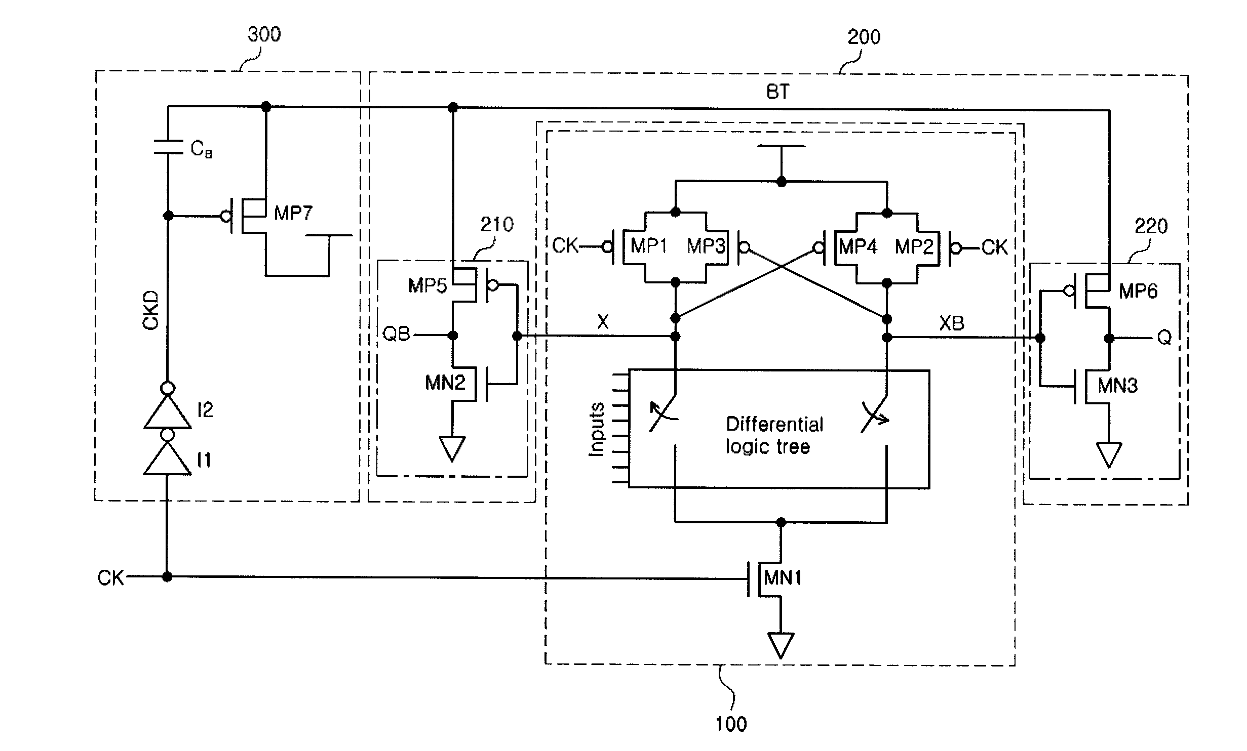
[0016]FIG. 3 is a diagram showing the construction of an apparatus for outputting complementary signals according to the embodiment of the present invention.

[0017]The complementary signal output apparatus includes a precharged differential logic block 100, a complementary output block 200, and a bootstrapping circuit block 300.

[0018]The precharged differential logic block 100 includes a differential logic tree and a plurality of switching means. In the embodiment of the present invention, the plurality of switching means is defined to include precharge transistors MP1 and MP2, keeper transistors MP3 and MP4, and a bottom transistor MN1. The switching means is not limited to transistors such as the above, but may be replaced with other elements depending on the level of those skilled in the art.

[0019]The differential logic tree performs a logic function, and is enabled...


PUM


Abstract

Disclosed herein is an apparatus for outputting complementary signals using bootstrapping technology. The apparatus for outputting complementary signals includes a precharaged logic block, one or more output nodes, and a bootstrapping circuit block. The precharged differential logic block generates a differential signal depending on an input signal. The one or more output nodes output the complementary signals depending on the differential signal. The bootstrapping circuit block is shared by the one or more output nodes, and amplifies the complementary signals.

Description

BACKGROUND OF THE INVENTION[0001]1. Field of the Invention[0002]The present invention relates generally to an apparatus for outputting complementary signals using bootstrapping technology, and, more particularly, to an apparatus for outputting complementary signals using bootstrapping technology, which can reduce a related area by improving the structures of a bootstrapping circuit block and the apparatus for outputting complementary signals and which can achieve high performance in low-power applications by increasing switching speed.[0003]2. Description of the Related Art[0004]As a result of the higher performance and diversification of portable electronic devices such as mobile phones, Personal Digital Assistants (PDAs) and Portable Multimedia Players (PMPs), the level of integration and operating frequency of circuits within the portable electronic devices are increasing, thereby resulting in an abruptly increasing power consumption.[0005]The methods of design for minimizing the...

Claims


Application Information

Patent Timeline
Patent Type & Authority Patents(United States)
IPC IPC(8): H03L5/00
CPCH03K19/01735H03K17/04H03K17/687
Inventor KONG, BAI-SUNJUNG, BYUNG-HWAKANG, SUNG-CHAN
Owner RES & BUSINESS FOUND SUNGKYUNKWAN UNIV
Why Eureka
Try Eureka