Active matrix display compensating method

a display device and active matrix technology, applied in the field of active matrix display devices, can solve the problems of screen uniformity, deterioration of the display quality of organic el displays, and extremely sensitive light emitted by organic el elements to tft characteristics, so as to achieve the effect of not reducing the aperture ratio of a bottom-emitting oled display and not increasing the complexity of the within-pixel circui

Active Publication Date: 2011-04-19
GLOBAL OLED TECH
View PDF9 Cites 9 Cited by
  • Summary
  • Abstract
  • Description
  • Claims
  • Application Information

AI Technical Summary

Benefits of technology

[0015]It is an advantage of the present invention that it can compensate for changes in the electrical characteristics of the thin-film transistors of an OLED display. It is a further advantage of this invention that it can so compensate without reducing the aperture ratio of a bottom-emitting OLED display and without increasing the complexity of the within-pixel circuits.
that it can compensate for changes in the electrical characteristics of the thin-film transistors of an OLED display. It is a further advantage of this invention that it can so compensate without reducing the aperture ratio of a bottom-emitting OLED display and without increasing the complexity of the within-pixel circuits.

Problems solved by technology

However, in this configuration, the intensity of light emitted by the organic EL element is extremely sensitive to the TFT characteristics.
This is a major cause of deterioration of the display quality of organic EL displays, in particular, screen uniformity.
Uncompensated, this effect can lead to “burned-in” images on the screen.
Additionally, changes in the EL element itself, such as forward voltage rise and efficiency loss, can cause image bum-in.
While such circuits can be used to compensate for changes in the threshold voltage of the driving transistor, they add to the complexity of the display, thereby increasing the cost and the likelihood of defects in the manufactured product.
For bottom-emitting devices, where the aperture ratio is important, such additional circuitry reduces the aperture ratio, and can even make such bottom-emitting displays unusable.

Method used


Image

  • Active matrix display compensating method
  • Active matrix display compensating method
  • Active matrix display compensating method

Examples


Embodiment Construction

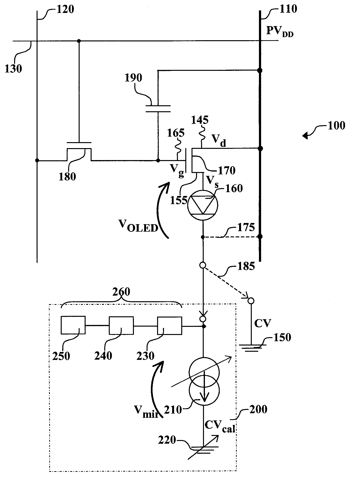
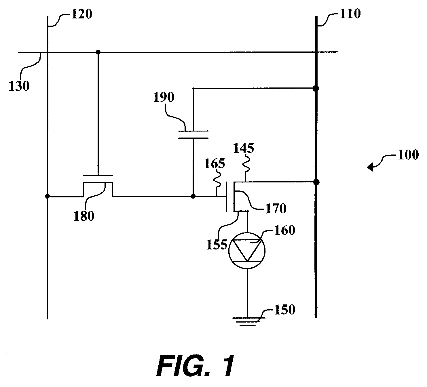
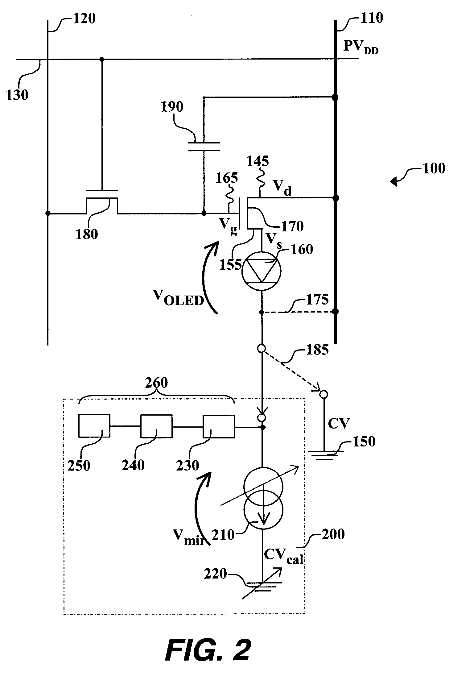
[0021]Turning now to FIG. 1, there is shown a schematic diagram of one embodiment of an OLED drive circuit that can be used in the practice of this invention. Such OLED drive circuits are well known in the art in active matrix OLED displays. OLED pixel drive circuit 100 has a data line 120, a power supply line or first voltage source 110, a select line 130, a drive transistor 170, a switch transistor 180, an OLED device 160 that can be a single pixel of an OLED display, and a capacitor 190. Drive transistor 170 is an amorphous-silicon (a-Si) transistor and has first electrode 145, second electrode 155, and gate electrode 165. First electrode 145 of drive transistor 170 is electrically connected to first voltage source 110, while second electrode 155 is electrically connected to OLED device 160. In this embodiment of pixel drive circuit 100, first electrode 145 of drive transistor 170 is a drain electrode and second electrode 155 is a source electrode. By electrically connected, it i...


PUM


Abstract

Compensating for changes in the threshold voltage of the drive transistor of an OLED drive circuit, the drive transistor includes a first electrode, second electrode, and gate electrode; connecting a first voltage source to the first electrode, and an OLED device to the second electrode and to a second voltage source; providing a test voltage to the gate electrode and connecting to the OLED drive circuit, a test circuit, that includes an adjustable current mirror causing voltage applied to the current mirror, to be at a first test level; providing a test voltage to the gate electrode of the drive transistor and connecting the test circuit to the OLED device producing a second test level after the drive transistor and the OLED device age; and using the first and second test levels to calculate changes in the voltage applied to the gate electrode of the drive transistor to compensate for drive transistor aging.

Description

CROSS-REFERENCE TO RELATED APPLICATIONS[0001]This is a continuation-in-part of commonly-assigned U.S. patent application Ser. No. 11 / 563,864, filed Nov. 28, 2006, now abandoned entitled “Active Matrix Display Compensation Method” by Charles I. Levey.FIELD OF THE INVENTION[0002]The present invention relates to an active matrix-type display device for driving display elements.BACKGROUND OF THE INVENTION[0003]In recent years, it has become necessary that image display devices have high-resolution and high picture quality, and it is desirable for such image display devices to have low power consumption and be thin, lightweight, and visible from wide angles. With such requirements, display devices (displays) have been developed where thin-film active elements (thin-film transistors, also referred to as TFTs) are formed on a glass substrate, with display elements then being formed on top.[0004]In general, a substrate forming active elements is such that patterning and interconnects formed...

Claims


Application Information

Patent Timeline
Patent Type & Authority Patents(United States)
IPC IPC(8): G09G3/30
CPCG09G3/3233G09G3/006G09G2320/043G09G2320/0295G09G2300/0842G09G3/30
Inventor LEVEY, CHARLES I.HAMER, JOHN W.
Owner GLOBAL OLED TECH
Why Eureka
Try Eureka