Two non-orthogonal states quantum cryptography method and apparatus with inter-and inter-qubit interference for eavesdropper detection

a quantum cryptography and inter-qubit interference technology, applied in the field of quantum cryptography, can solve problems such as noticeable perturbation

Inactive Publication Date: 2011-04-19
ID QUANTIQUE SA
View PDF16 Cites 13 Cited by
  • Summary
  • Abstract
  • Description
  • Claims
  • Application Information

AI Technical Summary

Benefits of technology

[0015]An apparatus and method are provided for exchanging between an emitter and a receiver a sequence of bits, also known as the raw key and allowing the emitter and the receiver to estimate the maximum amount of information an eavesdropper can have obtained on the raw key. This raw key can subsequently be distilled into a secure key through an appropriate key distillation procedure.
[0017]The first advantage of this quantum cryptography apparatus and method is that they are simple to implement. This simplicity stems from the fact that the qubits need to be prepared in only two non-orthogonal states. In addition, the apparatus and method allows the use of time coding of the values of the qubits. One of the bit values is coded by preparing a qubit consisting of a non-empty weak coherent state in a first of two time bins, while keeping the second time bin empty, with each time bin being shorter than the time between them. The other bit values is coded on a qubit where the empty and non-empty time bins are swapped. In addition, two qubits sent by the emitter must have a fixed phase relationship (they must be phase coherent). In this case, one of the optimal positive operator value measurement allowing to distinguish between the two states involves measuring the time of arrival of a photon with a photon counting detector. This measurement is extremely simple to perform. These states are moreover extremely robust against environmental perturbation in the quantum channel. Polarization fluctuations for example do not induce errors. Finally, this simplicity also means that high rate key exchange is possible, even with existing technology. Eavesdropping is monitored by an interferometric evaluation of the phase coherence between two time bins of two qubits by the receiver.

Problems solved by technology

This attribute stems from the fact that removal of qubits by an eavesdropper results in a noticeable perturbation.

Method used


Image

  • Two non-orthogonal states quantum cryptography method and apparatus with inter-and inter-qubit interference for eavesdropper detection
  • Two non-orthogonal states quantum cryptography method and apparatus with inter-and inter-qubit interference for eavesdropper detection
  • Two non-orthogonal states quantum cryptography method and apparatus with inter-and inter-qubit interference for eavesdropper detection

Examples


Embodiment Construction

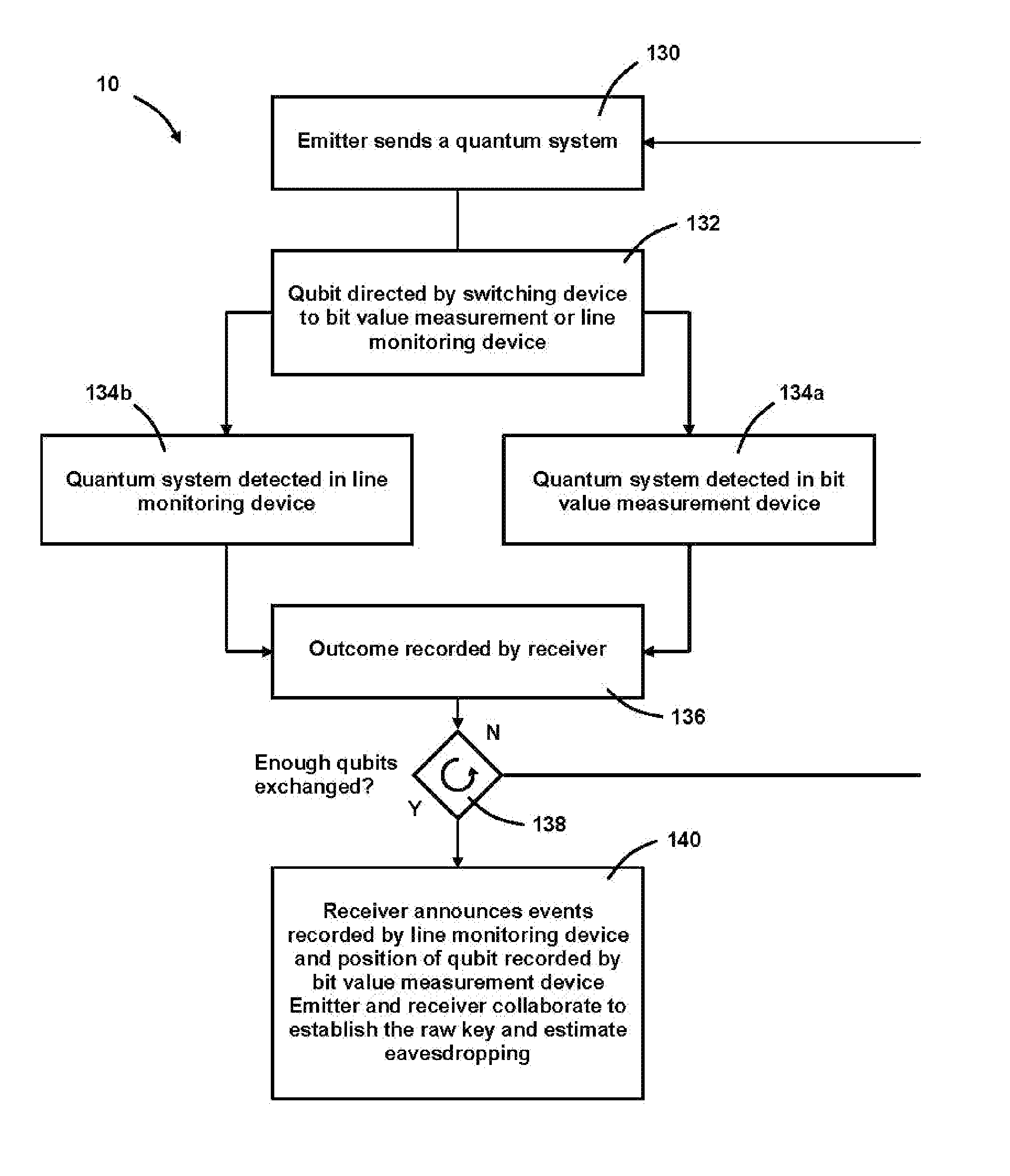
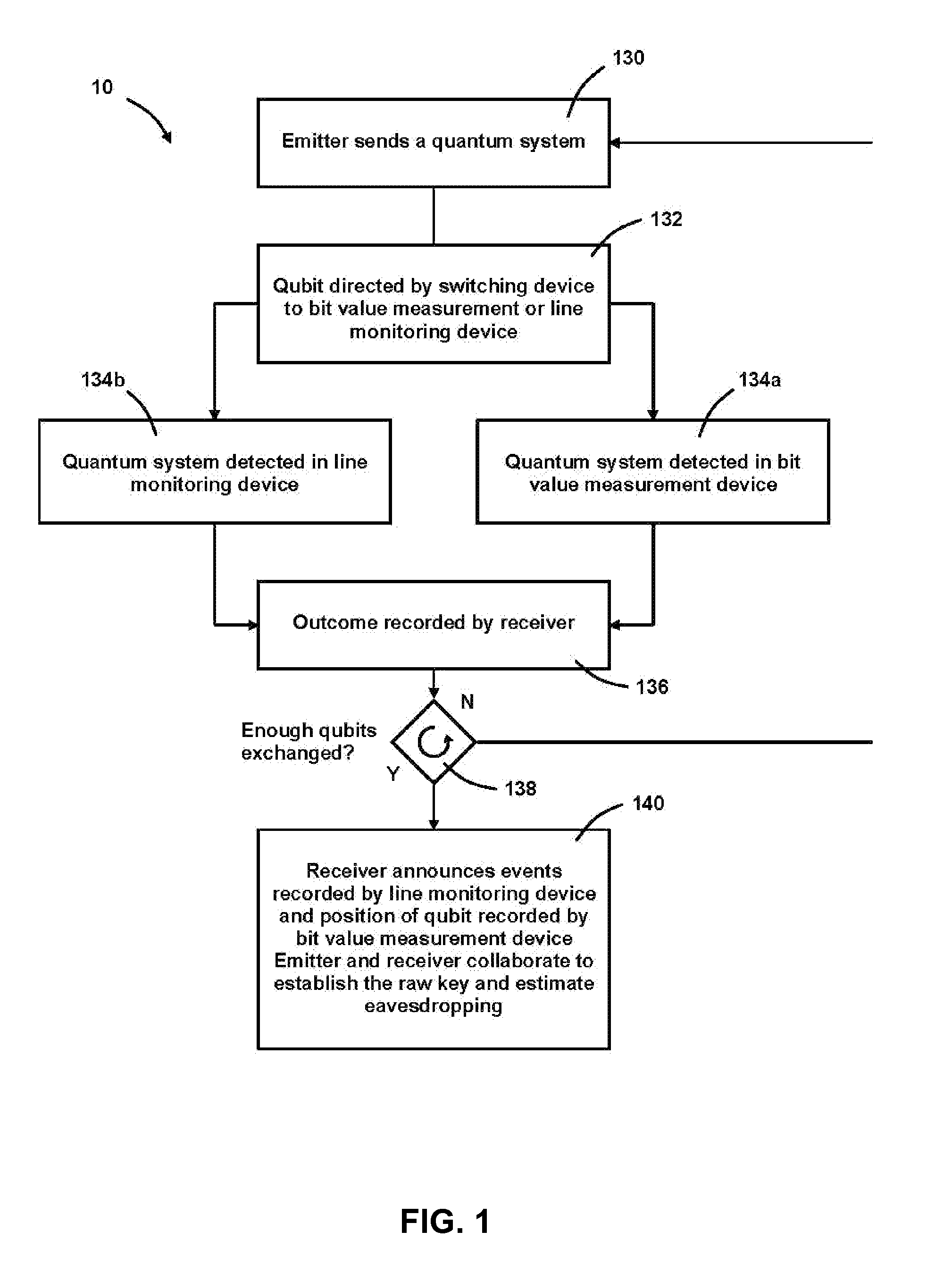
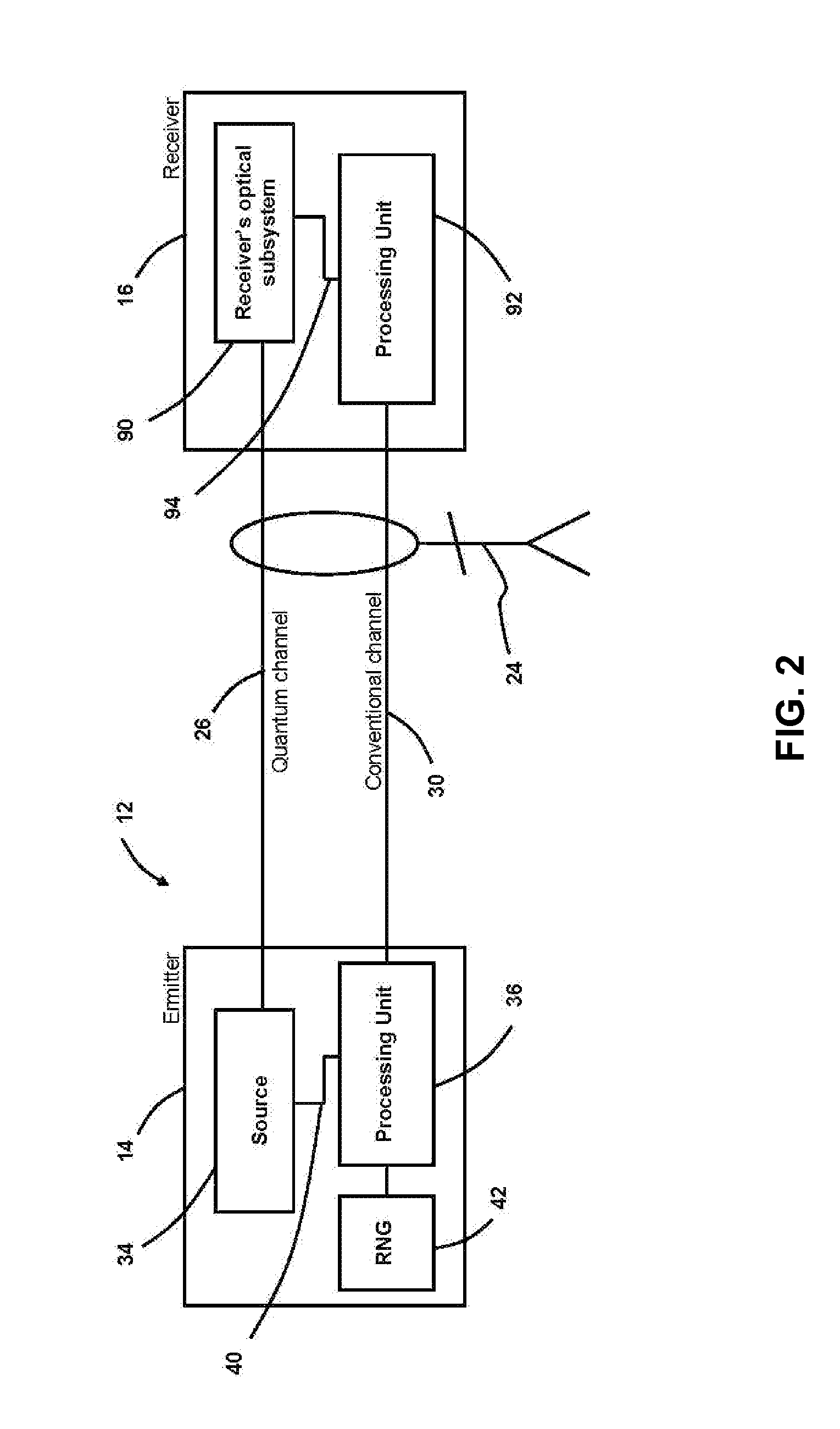
[0027]Referring now to FIGS. 1 and 2, a method 10 and apparatus 12 are provided for exchanging between an emitter station 14 and a receiver station 16 a sequence of symbols coded on a stream 22 of quantum systems (i.e., qubits) 20, shown in FIG. 3, used to transmit the raw key (a data string such as 101100101001111001001010 . . . 01010100) and allowing the emitter station and the receiver station to estimate the maximum amount of information an eavesdropper 24 can have obtained on the raw key. This raw key can subsequently be distilled into a secure key (a distilled data string such as 10011000 . . . 1100 of fewer digits than the raw data string) through an appropriate key distillation procedure, known in the art.

[0028]The emitter station 14 and the receiver station 16 are connected by a quantum channel 26 and a conventional channel 30. The values of the symbols are encoded by preparing quantum systems in a particular quantum state, also known as a data state. The quantum systems ex...


PUM


Abstract

An apparatus and method for implementing a secure quantum cryptography system using two non-orthogonal states. For each qubit, the to emitter station prepares a quantum system in one of two non-orthogonal quantum states in the time-basis to code bit values. Intra- and inter-qubit interference is then used to reveal eavesdropping attempts. Witness states are used to help reveal attacks performed across the quantum system separation.

Description

CROSS REFERENCE TO RELATED APPLICATIONS[0001]This application is the National Stage of International Application No. PCT / IB05 / 02622, filed Sep. 1, 2005, which claims the benefit of U.S Provisional Application No. 60 / 606,793, filed Sep. 2, 2004.BACKGROUND OF THE INVENTION[0002]1. Field of the Invention[0003]This invention relates generally to the field of quantum cryptography, and more particularly to an apparatus and method for allowing two users to exchange a sequence of bits and to confirm its secrecy.[0004]2. Description of the Prior Art[0005]If two users possess shared random secret information (below the “key”), they can achieve, with provable security, two of the goals of cryptography: 1) making their messages unintelligible to an eavesdropper and 2) distinguishing legitimate messages from forged or altered ones. A one-time pad cryptographic algorithm achieves the first goal, while Wegman-Carter authentication achieves the second one. Unfortunately both of these cryptographic ...

Claims


Application Information

Patent Timeline
Patent Type & Authority Patents(United States)
IPC IPC(8): H04K1/00
CPCH04L9/0858
Inventor GISIN, NICOLASRIBORDY, GREGOIREZBINDEN, HUGO
Owner ID QUANTIQUE SA
Why Eureka
Try Eureka