
Method for detecting overpressure inside a compartment associated with a gas turbine nacelle

Active Publication Date: 2011-04-26
ROLLS ROYCE PLC
View PDF7 Cites 13 Cited by
  • Summary
  • Abstract
  • Description
  • Claims
  • Application Information

AI Technical Summary

Benefits of technology

A problem associated with nacelles is that of “overpressure”, where failure in an associated pressure system causes an i

Problems solved by technology

A problem associated with nacelles is that of “overpressure”, where failure in an associated pressure system causes an increase in pressure inside the nacelle, potentially leading to a “burst condition” and consequent breach of the nacelle.
Failure of one of these high pressure ducts or valves may lead very quickly to a critical overpressure situation inside the respective compartment.
At the same time, the respective fire warning system will not activate until such time as the associated fire zone temperature actually represents a critical fire-risk.
In practice therefore for a given fire zone, there may be an overpressure detection “gap” whereby a given leakage mass flow into a fire zone may be sufficiently high to “choke” the respective ventilation outlet and cause critical overpressure within the fire zone, but the temperature is nevertheless insufficient to trigger the respective fire-warning system.

Method used


Image

  • Method for detecting overpressure inside a compartment associated with a gas turbine nacelle
  • Method for detecting overpressure inside a compartment associated with a gas turbine nacelle
  • Method for detecting overpressure inside a compartment associated with a gas turbine nacelle

Examples


Embodiment Construction

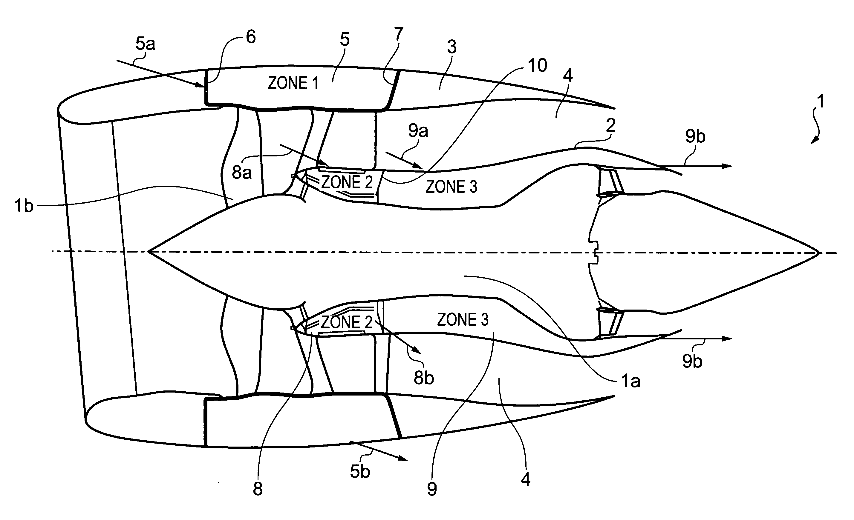
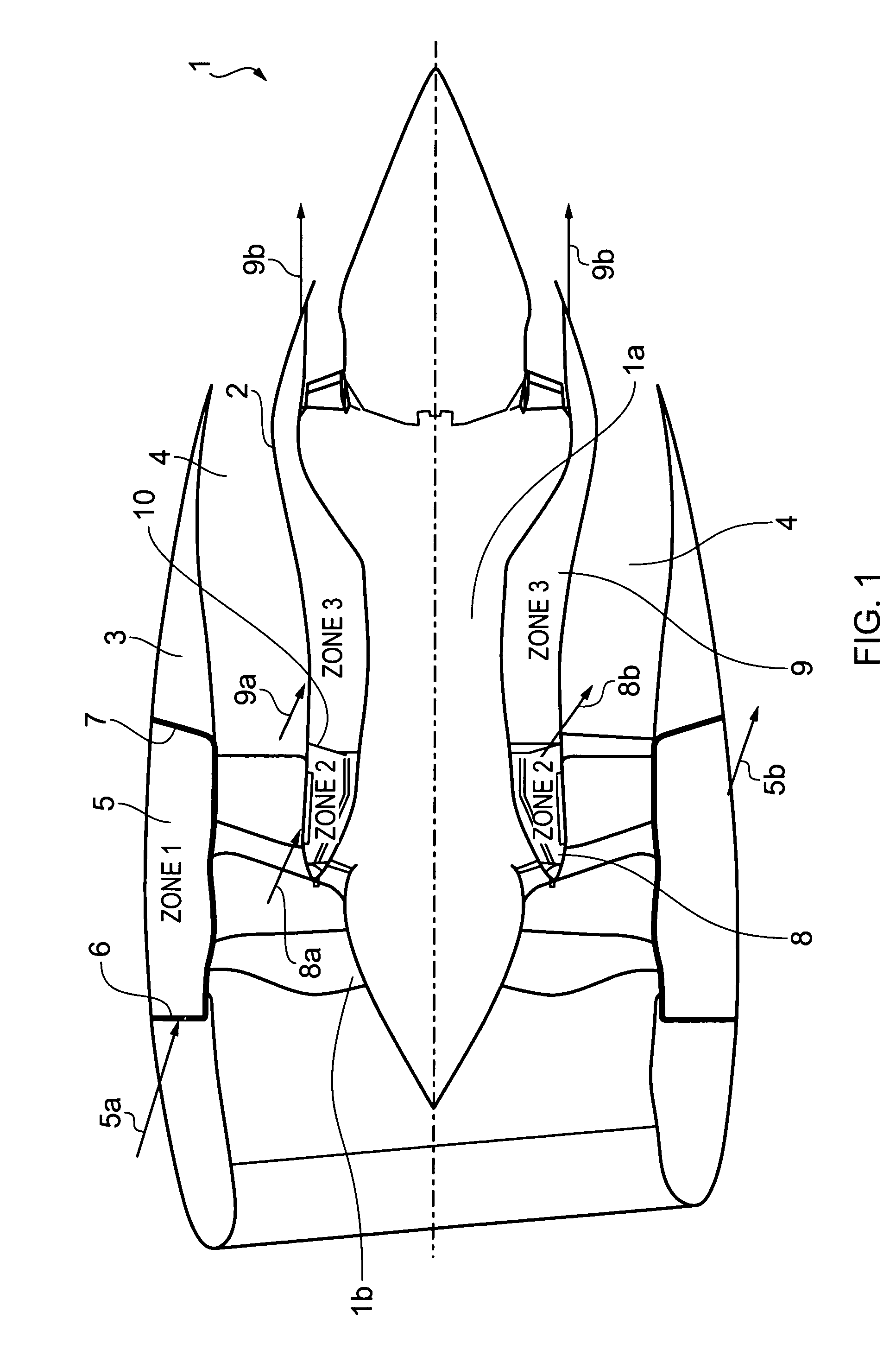
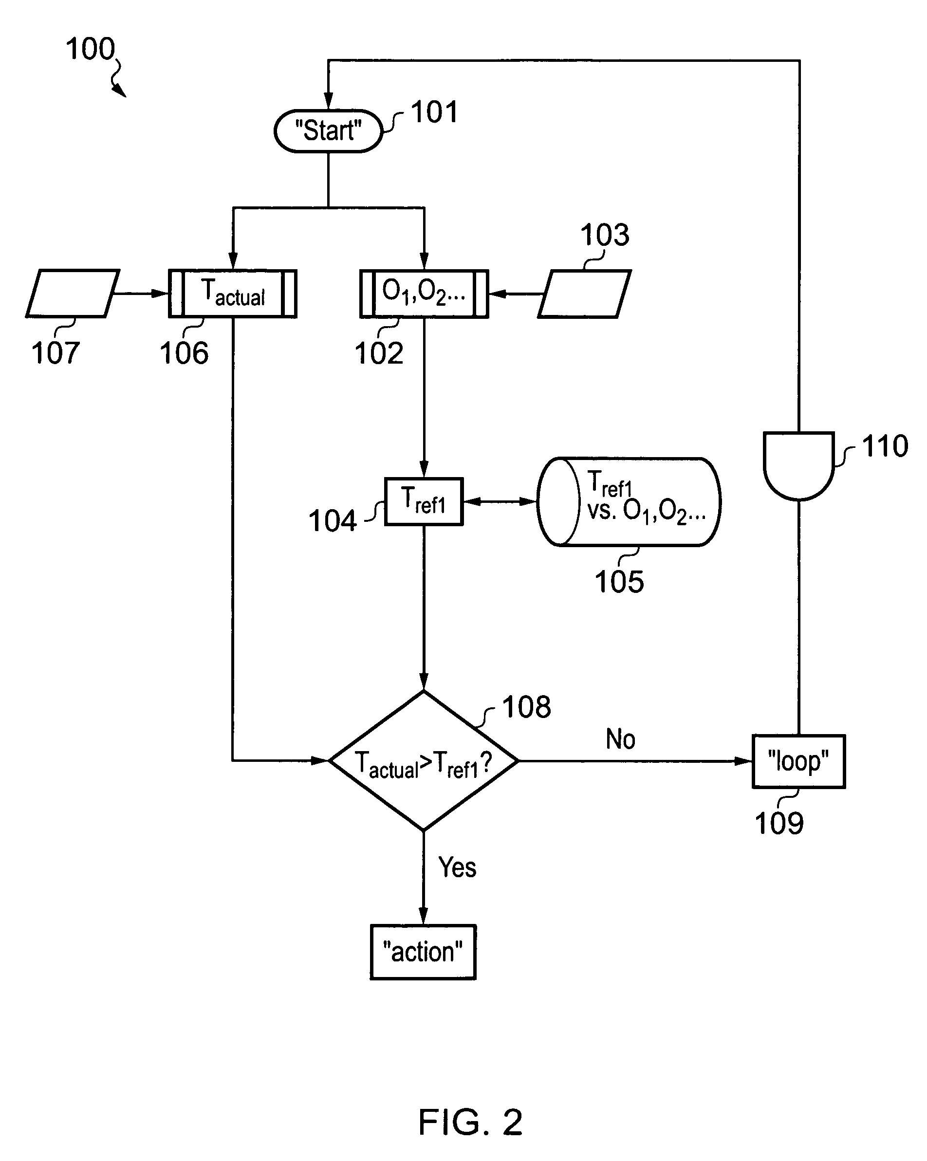
FIG. 2 illustrates a method 100 which may be implemented in a gas turbine application, such as the turbofan engine 1 of FIG. 1, in order to monitor the pressure inside a designated compartment for detecting an overpressure inside the compartment. Following detection of an overpressure, the method 100 additionally prompts mitigating action in order to reduce said overpressure inside the compartment with the intention of avoiding a “burst condition” developing in the compartment.

It is envisaged that the method 100 will be implemented using a suitably configured processor or set of “distributed” processors. Each processor may be a dedicated processor, or may be shared with some other system forming part of the gas turbine.

The method 100 is as follows:

A “Start” command is issued by a processor at step 101.

Following issue of the “Start” command, at step 102 a processor is used to determine one or more operating conditions O1, O2 . . . on the basis of a corresponding sensor input 103.

Each...


PUM


Abstract

A method, for detecting overpressure inside a compartment associated with a gas turbine nacelle, includes: a) measuring one or more predetermined operating conditions nominally affecting the temperature inside the compartment; b) determining a reference temperature for the compartment, corresponding to a nominal reference zone pressure, on the basis of the measured operating condition or conditions; c) measuring the actual temperature inside the compartment, corresponding to the actual compartment pressure; and d) using the measured actual temperature in the compartment and the determined reference temperature for the compartment to assess the gas pressure inside the compartment. A system for assessing the gas pressure inside the compartment caused by an associated pressure system failure includes using a quantified mass leakage flow to assess gas pressure inside the compartment. The quantified mass leakage flow may also be used to detect excessive mass leakage flow by comparing the quantified mass leakage flow with a predetermined mass flow leakage.

Description

BACKGROUNDThe present invention relates to a method for detecting overpressure inside a compartment associated with a gas turbine nacelle, including so-called “fire zones” formed by a fan nacelle or a core nacelle surrounding a jet engine in an aircraft.Gas turbines may be provided with a nacelle. In aerospace applications in particular, it is common for a gas turbine engine to be fitted with one or more such nacelles.By way of example, FIG. 1 shows a simplified cross-sectional overview of a typical turbofan engine 1 in a civil aircraft.The engine 1 is supported inside two nacelles: an inner, core nacelle 2 which surrounds the engine core 1a, and an outer, hollow-wall fan nacelle (or “fancase”) 3 which surrounds the by-pass fan 1b. The outer surface of the core nacelle 2 and the inner surface of the fan nacelle 3 together define an annular fan discharge passageway 4 for the respective bypass jet from the bypass fan 1b. In order to limit the spread of a fire throughout the respective...

Claims


Application Information

Patent Timeline
IPC IPC(8): G01M15/14
CPCF02C9/16F02K9/54F05D2260/602F05D2260/81F05D2260/821F02C7/24F01D21/10F01D21/12G01M15/048G01M15/102G01M15/14
Inventor RUSTON, SIMON M.
Owner ROLLS ROYCE PLC
Learn More