Three-pass heat exchanger for an EGR system

a heat exchanger and exhaust gas technology, applied in indirect heat exchangers, machines/engines, lighting and heating apparatus, etc., can solve the problems of gas loss, inability to exceed the length given in each case, and the separation of the inlet from the outlet, etc., and achieve the effect of less cos

Inactive Publication Date: 2011-04-26
DYTECH ENSA +1
View PDF12 Cites 6 Cited by
  • Summary
  • Abstract
  • Description
  • Claims
  • Application Information

AI Technical Summary

Benefits of technology

[0025]The exchanger may include a bypass valve, in which case one of these three differentiated areas for gas circulation performs the function of a bypass line which, as the case may be, can be insulated by means of a double pipe, assuring extremely reduced efficiency when the bypass function is performed.
[0031]Less fouling, therefore the part has a smaller loss of efficiency.
[0032]It is not necessary to use a casting piece at the inlet, possibly replacing it with foundries, which are much simpler and less expensive.

Problems solved by technology

This is the loss of pressure in the gas due to friction, changes of section and other turbulences that the gas experiences while traveling through the part.
When designing a heat exchanger for an EGR system, it is also necessary to take into account the available space in the engine, so a given length in each case cannot be exceeded for the purpose of improving the efficiency of the part.
However, a casting piece must be used at the inlet, separating the inlet from the outlet, notably making it more expensive.
The need to use this external pipe complicates the designs due to the lack of space in most engines, and on many occasions making the use of this type of exchangers unfeasible.

Method used


Image

  • Three-pass heat exchanger for an EGR system
  • Three-pass heat exchanger for an EGR system
  • Three-pass heat exchanger for an EGR system

Examples


first embodiment

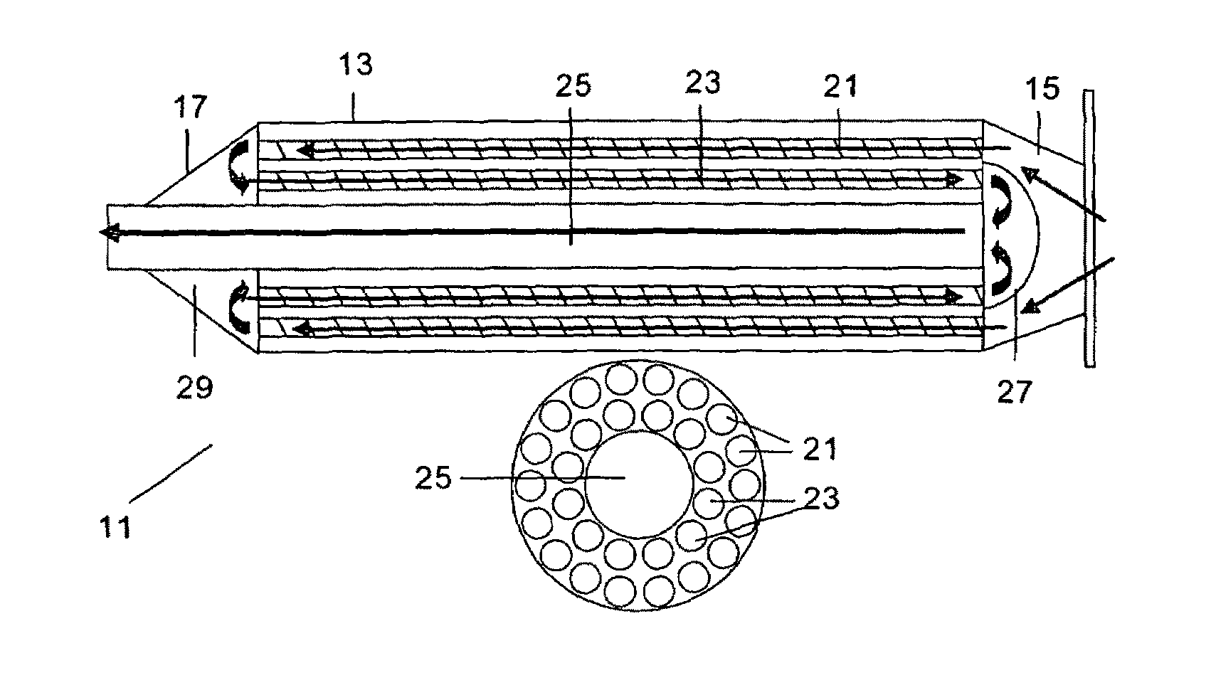
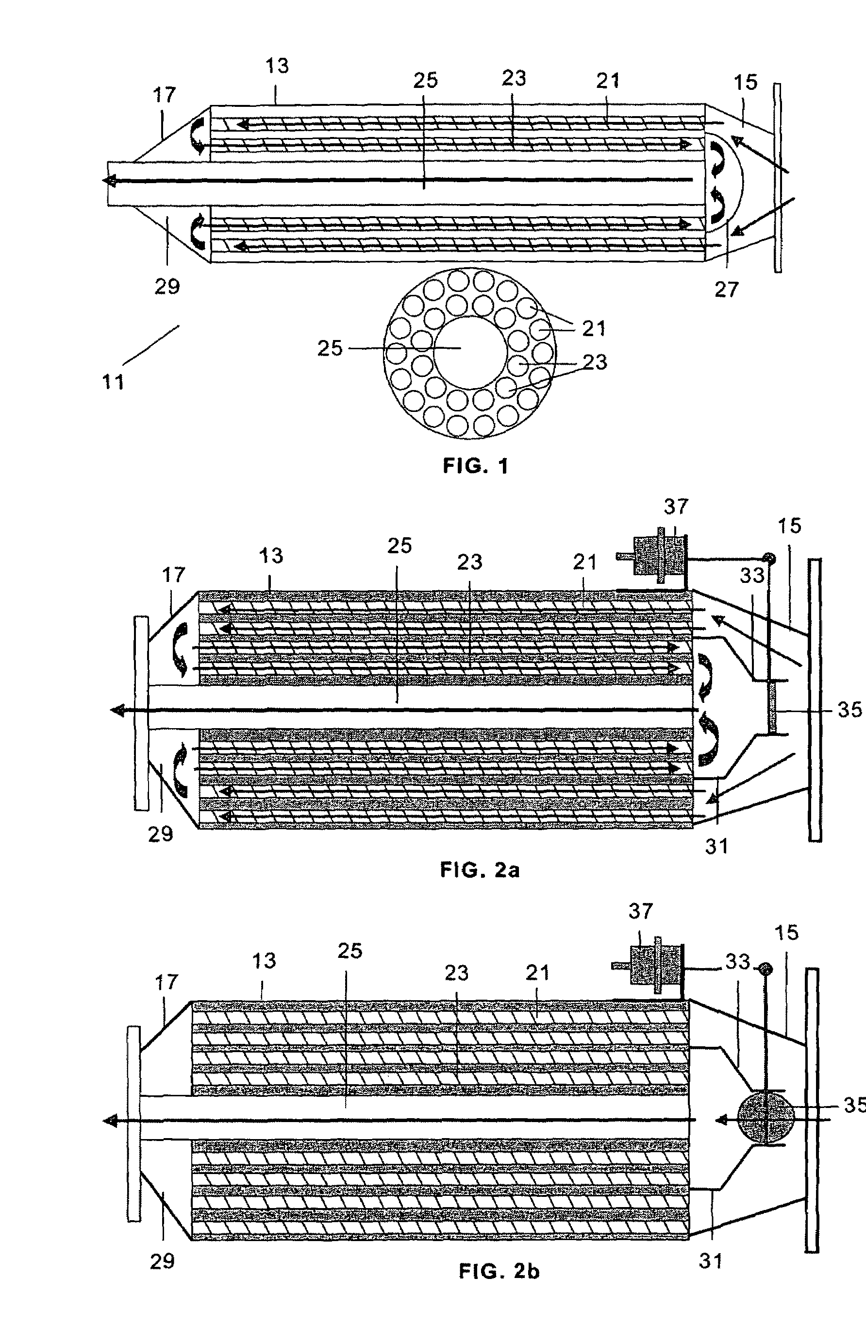
[0040]In the invention, shown in FIG. 1, the exchanger 11 comprises a casing 13, the inside of which houses a cooling chamber with coolant inlet and outlet pipes (not shown), an inlet head 15 and an outlet head 17. The three differentiated gas circulation areas are concentric areas 21, 23, 25, the outer area 21 and intermediate area 23 formed by a plurality of pipes arranged in ring shape. The inner area 25 can be formed by a single pipe, as shown in FIG. 1, with a much lower heat exchange level than the other areas, or by a plurality of pipes like the other two areas, depending on the gas cooling requirements.

[0041]It must be observed that the concentric pattern of the cooling areas 21, 23 contributes to less fouling of the exchanger and therefore to an increase in its efficiency since:[0042]The fouling dramatically increases when the gas is colder.[0043]The fouling is reduced if the gas turbulence, i.e. the rate of passage of the gas through the pipes, is increased, therefore if t...

third embodiment

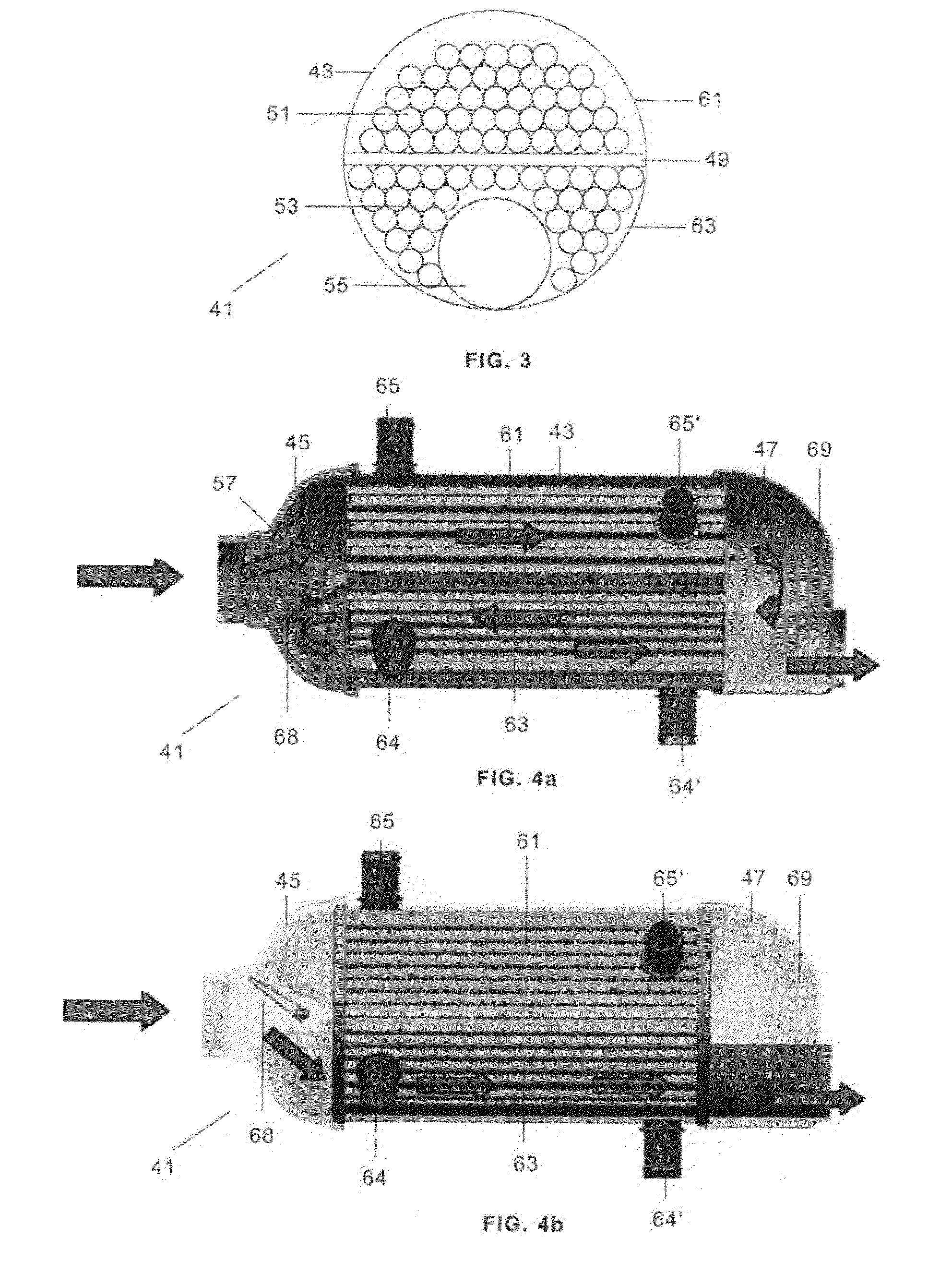
[0054]In the invention shown in FIGS. 4a and 4b, there are two cooling chambers 61, 63 of a semicircular section that are separated by a central plate 49, with different coolant inlet 65, 64 and outlet 65′, 64′ pipes, an inlet head 45 and an outlet head 47. The two cooling chambers 61, 63 are separated so as to be able to operate with coolants at different temperatures, for example 110° C. and 60° C.

[0055]The cooling chamber at the higher temperature 61 houses the first gas circulation area 51 through a plurality of pipes. The cooling chamber at the lower temperature 63 houses the second gas circulation area 53, formed by a plurality of pipes and the third one is formed by a single pipe 55 with a much lower heat exchange level than the other areas.

[0056]The inlet head 45 includes a part 57 incorporating a bypass valve 68 with an actuator 77, of the type disclosed in Spanish patent number 2,223,217, and the outlet head 47 has a distribution chamber 69 collecting the gas exiting area ...

fourth embodiment

[0058]the invention is similar to the third embodiment without the bypass valve. In this case, the part 57 is configured so as to on one hand close off the access of the inlet gas to the second area 53 and the third area 55, but allowing its passage to the first area 51 and, on the other hand, to facilitate gas circulation from the second area 53 to the third area 55.


PUM


Abstract

The present invention relates to a three-pass heat exchanger for an EGR system, comprising a casing housing at least one cooling chamber for gas circulating through a plurality of pipes and heads on its ends coupled to the gas inlet pipe coming from the exhaust manifold and to the gas outlet pipe connected to the intake manifold of the engine, which is configured as a three-pass heat exchanger, i.e. with three differentiated areas for gas circulation from the inlet pipe to the outlet pipe, the inlet pipe and the outlet pipe being located at opposite ends of the exchanger. The exchanger can include a bypass valve and two cooling chambers at different temperatures.

Description

FIELD OF THE INVENTION[0001]The present invention relates to a heat exchanger for an exhaust gas recirculation (EGR) system for an internal combustion engine, and more particularly to a heat exchanger with three differentiated passes of gas circulation within it.BACKGROUND OF THE INVENTION[0002]Different exhaust gas recirculation systems in internal combustion engines, called EGR systems, are known in the current state of the art.[0003]These systems recirculate exhaust gases from the exhaust manifold to the intake manifold of the engine after subjecting them to a cooling process for the purpose of reducing the amount of NOx emissions.[0004]The cooling process is carried out in heat exchangers formed by cooling chambers housing a group of pipes through which the gas passes that are surrounded by a coolant undergoing permanent recirculation.[0005]Single-pass heat exchangers in which the exhaust gas enters at one end, is distributed among said pipes and exits at the opposite end at a l...

Claims


Application Information

Patent Timeline
Patent Type & Authority Patents(United States)
IPC IPC(8): F02B47/08F02B47/00
CPCF02M25/0729F02M25/0737F28D7/1638F28F27/02F28D7/1676Y02T10/121F28D21/0003F28F2250/06F02M26/26F02M26/32F02D21/08
Inventor CASTA{HACEK OVERGRANDE FERNANDEZ, JOSE ANTONIO
Owner DYTECH ENSA
Why Eureka
Try Eureka