Oil mist separator

a technology separator body, which is applied in the field of oil mist separator, can solve the problems of serious environmental harm, large lampblack, and large oil mist, and achieve the effects of low volume, simple profile and easy assembly and repair

Inactive Publication Date: 2011-04-26
SAN FORD MACHINERY
View PDF32 Cites 8 Cited by
  • Summary
  • Abstract
  • Description
  • Claims
  • Application Information

AI Technical Summary

Benefits of technology

[0007]An oil mist separator according to this invention mainly comprises a body inside which a container is formed. A first spacer and a second spacer are formed in an inner layer of the container to form an exhaust chamber, a filtering chamber, and an oil collection chamber from top to bottom in the container. Further, through an air intake unit serving as an air blower, the oil mist is directly transmitted to the filtering chamber. Next, through a filtering unit, the oil mist is separated. The filtering unit is made up with several centrifugal dust collectors. Each of the centrifugal dust collectors is mainly provided with a hollow duct. One end of the duct is forwards convergent and formed into a convergent portion of which the end is formed with a mouth, while the other end of the duct is covered with a lid. A hollow nozzle going axially along the duct is provided passing through the lid. The two ends of nozzle are respectively formed into a guidance inlet and a guidance outlet. The guidance inlet lies in the convergent portion. Besides, one side of the body is formed with a prolonged portion parallel with its axis. A flowing passage communicating with the duct is formed in the prolonged portion, and a flowing port is formed at a free end of the prolonged portion. Further, the mouth of centrifugal dust collector passes through the first spacer. A guidance outlet of the centrifugal dust collector passes through the second spacer. Thus, the oil mist sent into the air intake unit may enter the duct from the flowing port and go spirally forward to the mouth along the inner wall of duct to form a spiral air stream, and with a centrifugal force caused by the spiral air stream, the oil mist of which the mass is heavier than the air is made to separate from the air and enters the oil collection chamber of the body from the mouth for collection and recovery. Then, the air of zero pollution that separates from the oil mist enters the exhaust chamber from the nozzle and, after being gathered in the exhaust chamber, is extracted to the outdoors. Thus, no filter net is required and the oil mist may even separate from the air, which protects the environment, and the oil mist separator is designed with modularity, so it is easy to assemble and repair. Further, the volume of oil mist separator is low and its profile is simple and of fashion; it is not abrupt even if the separator is used in a system kitchen. Next, the recycled oil mist may be made into a low-level oil product or a release agent used in the building industry for achievement of the effect of recycling.

Problems solved by technology

Generally, a medium or large catering industry frequently causes much lampblack during operation, and a factory also frequently causes much oil mist during operation when using cutting oil or cooling oil.
However, the way of using the kitchen ventilator to directly extract the lampblack and oil mist to the outdoors will do serious harm to the environment.
Although there is filter net installed on an exhaust passage in reaching the effect of filtering, the effect is limited.
When being used for a period of time, the filter net is blocked and must be replaced, and especially when being used in a work environment where the oil mist is caused, the filter net is even replaced frequently, which puts the working personnel to annoyance.
Further, the replaced filter net that is stained with greasy dirt has to be thrown away, which indirectly pollutes the environment and does not meet the requirement of environmental protection.

Method used


Image

  • Oil mist separator
  • Oil mist separator
  • Oil mist separator

Examples


Embodiment Construction

[0014]Now, the present invention will be described more specifically with reference to the following embodiments. It is to be noted that the following descriptions of preferred embodiments of this invention are presented herein for purpose of illustration and description only; it is not intended to be exhaustive or to be limited to the precise form disclosed.

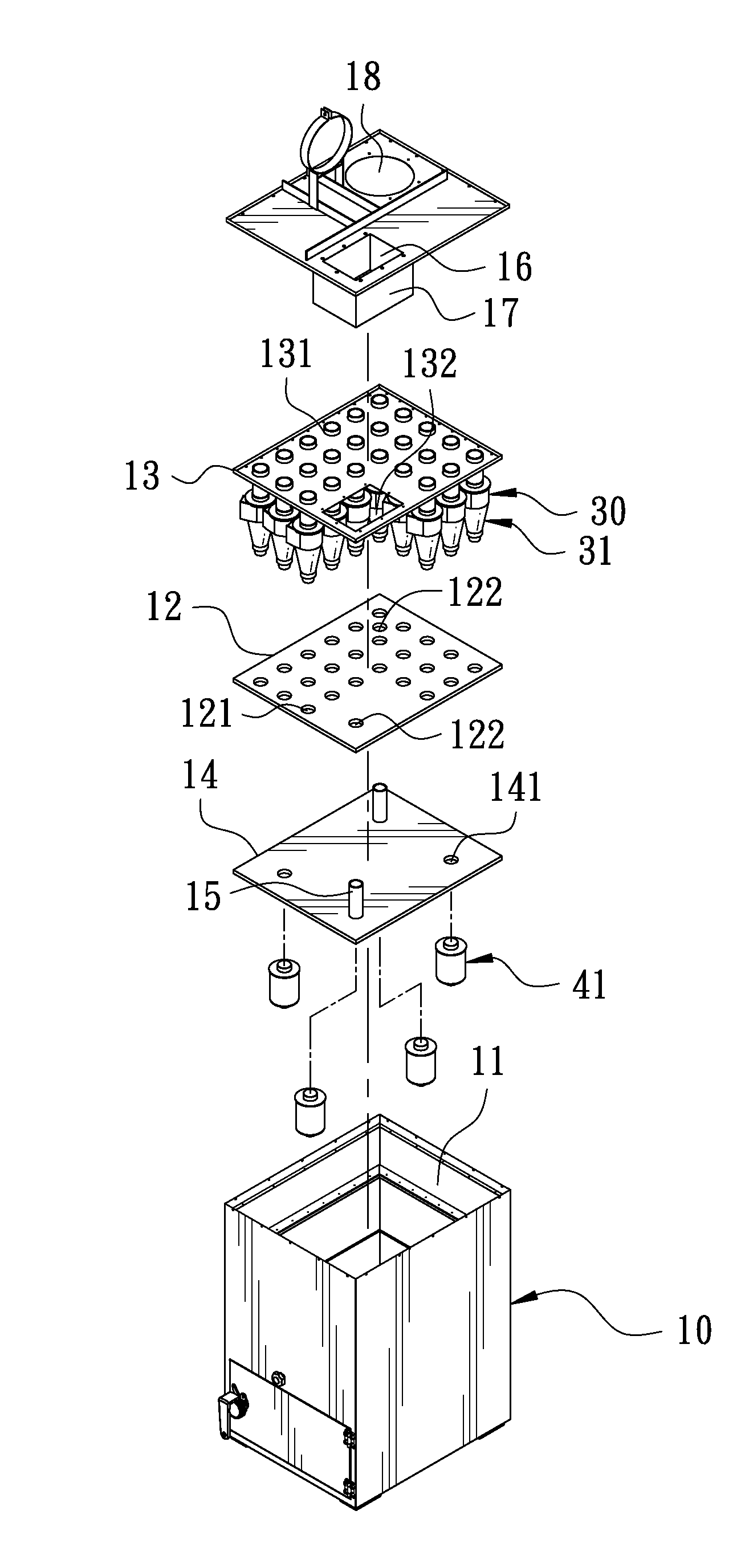
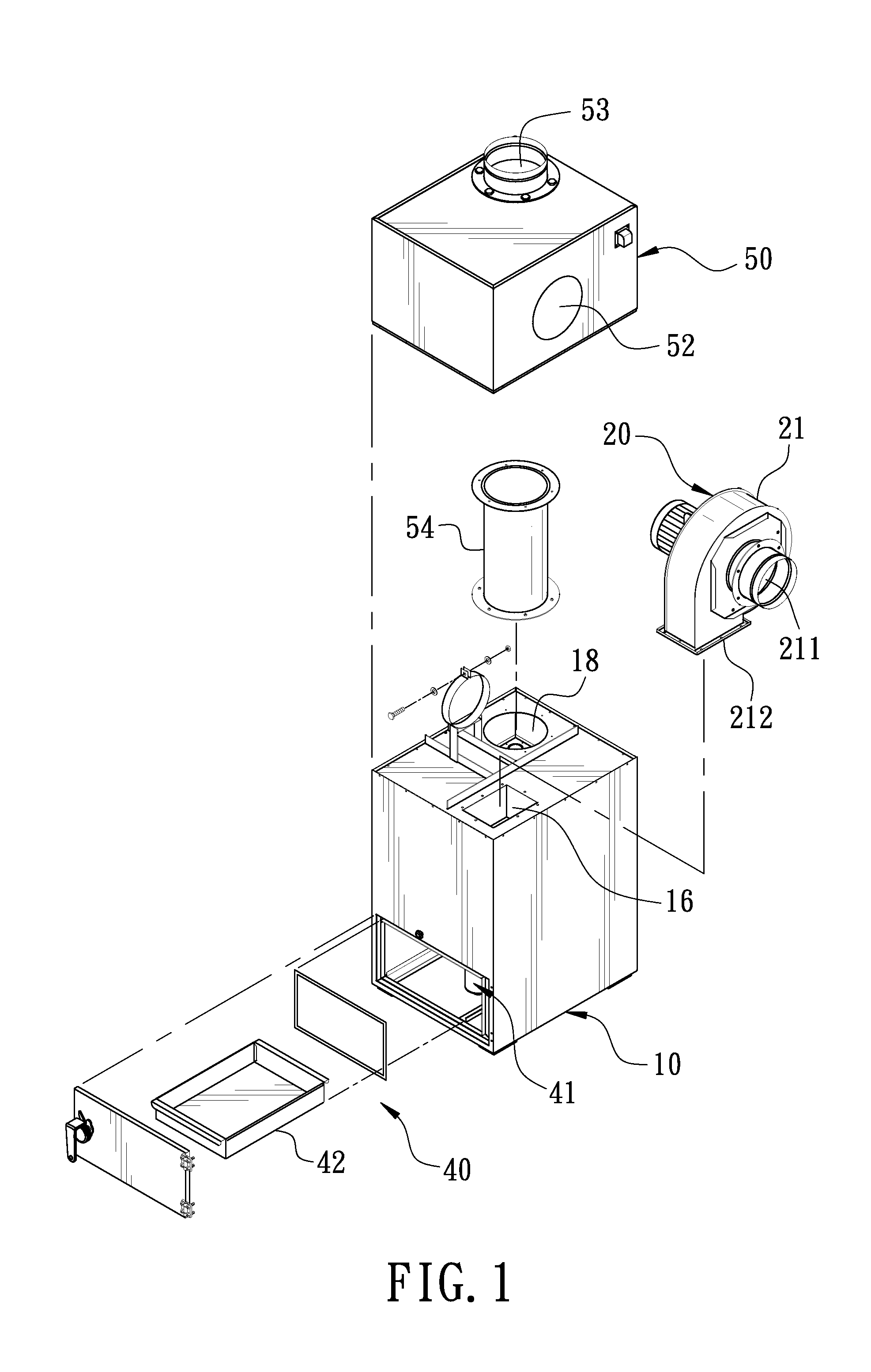
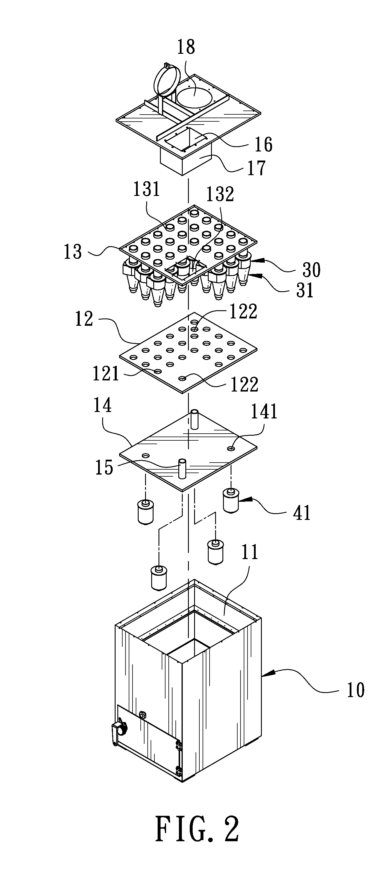
[0015]With reference to FIGS. 1 and 2 and with cross reference to FIG. 3 shown respectively as a 3D exploded view of an oil mist separator according to this invention, a 3D exploded view of the body, and a sectional view of the body, the oil mist separator mainly comprises a body 10, an air intake unit 20, a filtering unit 30, and an oil collection unit 40.

[0016]A container 11 is formed in the body 10, and a first spacer 12 and a second spacer 13 are formed and pile in an inner layer of the container 11 to form an exhaust chamber 111, a filtering chamber 112, and an oil collection chamber 113 from top to bottom in the container ...


PUM

PropertyMeasurementUnit
diameteraaaaaaaaaa
massaaaaaaaaaa
volumeaaaaaaaaaa

Abstract

An oil mist separator includes a body inside which a filtering chamber is formed for a filtering unit made up with several centrifugal dust collectors. With an air intake unit, the outside oil mist is sent into the filtering chamber. Then, the centrifugal dust collectors are used to cause a spiral airstream. With a centrifugal force caused by the spiral airstream, the oil mist is made to separate from the air. Next, the filtered air of zero pollution is vented to the atmosphere, and the separated oil mist is collected and recycled. Thus, the oil mist may be separated and the recycled oil mist may be made into a low-level oil product or a release agent used in the building industry for achievement of the effect of environmental protection.

Description

BACKGROUND OF THE INVENTION[0001]1. Field of the Invention[0002]This invention relates to an oil mist separator.[0003]2. Description of the Prior Art[0004]Generally, a medium or large catering industry frequently causes much lampblack during operation, and a factory also frequently causes much oil mist during operation when using cutting oil or cooling oil. In order to avoid the lampblack and oil mist from causing turbid air indoors and then affecting an operator's mood and even endangering a human body, a kitchen ventilator is installed in the environment to extract the lampblack and oil mist.[0005]However, the way of using the kitchen ventilator to directly extract the lampblack and oil mist to the outdoors will do serious harm to the environment. Although there is filter net installed on an exhaust passage in reaching the effect of filtering, the effect is limited. When being used for a period of time, the filter net is blocked and must be replaced, and especially when being used...

Claims


Application Information

Patent Timeline
Patent Type & Authority Patents(United States)
IPC IPC(8): B01D45/12
CPCB01D45/16Y10S55/46
Inventor CHENG, MAO-NAN
Owner SAN FORD MACHINERY
Why Eureka
Try Eureka