Method and device for reducing the speed in the event of breakage of a gas turbine engine turbine shaft

a technology of gas turbine engine and turbine shaft, which is applied in the direction of machines/engines, sustainable transportation, mechanical equipment, etc., can solve problems such as significant heating

Active Publication Date: 2011-05-03
SN DETUDE & DE CONSTR DE MOTEURS DAVIATION S N E C M A
View PDF13 Cites 6 Cited by
  • Summary
  • Abstract
  • Description
  • Claims
  • Application Information

AI Technical Summary

Benefits of technology

[0005]The present invention is aimed at a simple and effective method for reducing the rotational speed, in a gas turbine engine, of a turbine comprising a rotor driving a shaft and able to rotate inside a stator, in the event of breakage of said shaft.
[0007]The rotor needs to move only a very short axial distance before it comes into contact with the stator and very quickly causes significant heating through friction. This is because the powers involved are high. Measuring the temperature is therefore a very effective indicator liable very quickly to reach a level characteristic of shaft breakage. Practically simultaneously shutting off the fuel supply makes it possible to avoid the onset of overspeed or, at the very least, to limit it by removing the main supply of energy to the turbine rotor. This measure leads to an increase in the bursting margin which may result in an increase in safety, a saving in mass, or alternatively a saving on the strength that the rotating parts need to have.
[0009]According to another feature, the temperature threshold is above the maximum temperature liable to be reached while the engine is running. This then avoids the risks of error due to reingurgitation of hot gases in particular.
[0011]According to another feature, the sensor or sensors is or are thermocouple sensors and comprise a probe fixed to the stator by means of a ceramic or metallic coating. This measure allows the thermocouple probe to be positioned a short distance from the adjacent rotor while at the same time protecting it during normal running so that contact between the rotor and the stator leads to rapid heating of the thermocouple probe so that swift action can be taken with regard to the fuel supply.

Problems solved by technology

The rotor needs to move only a very short axial distance before it comes into contact with the stator and very quickly causes significant heating through friction.

Method used


Image

  • Method and device for reducing the speed in the event of breakage of a gas turbine engine turbine shaft
  • Method and device for reducing the speed in the event of breakage of a gas turbine engine turbine shaft

Examples


Embodiment Construction

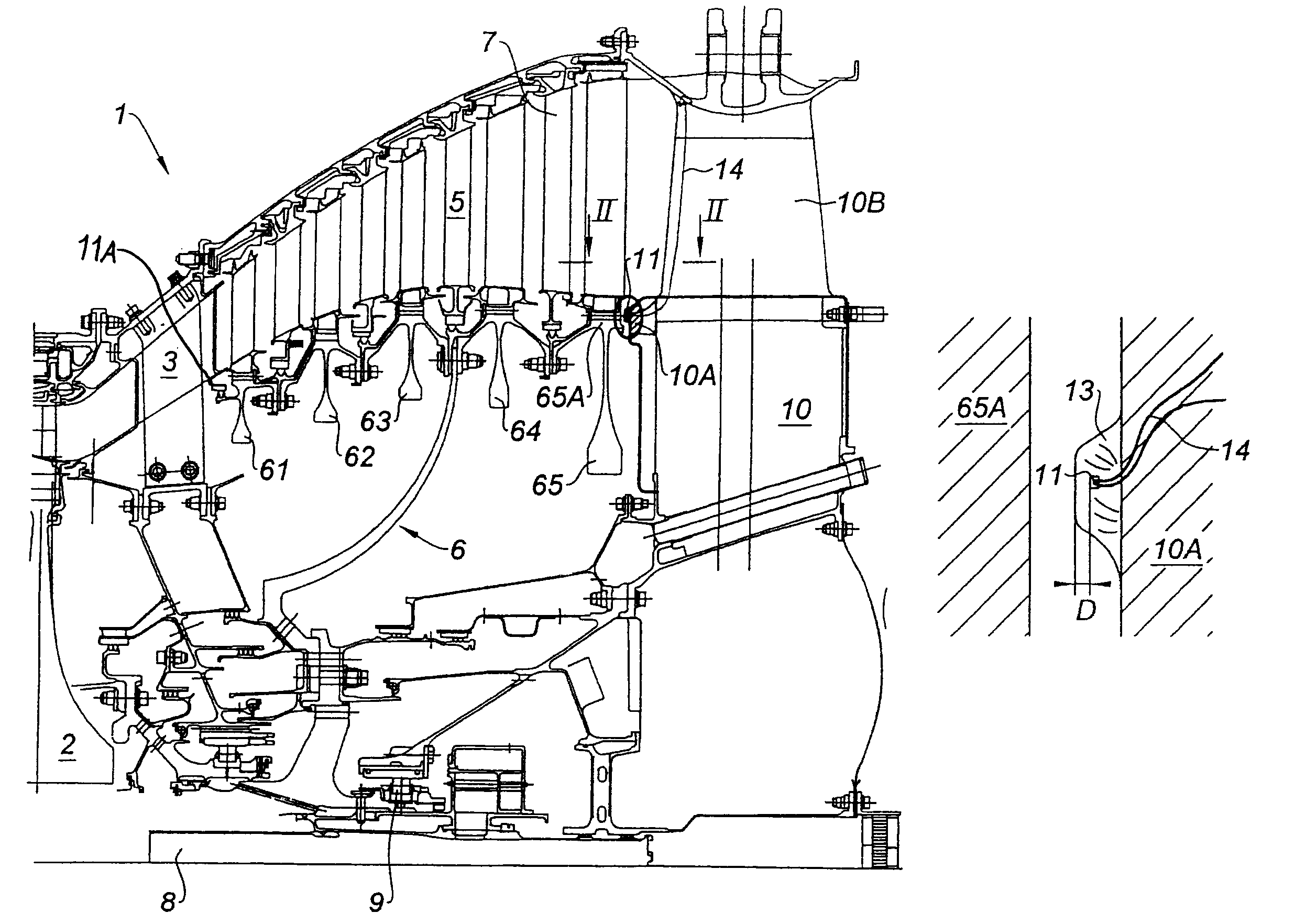
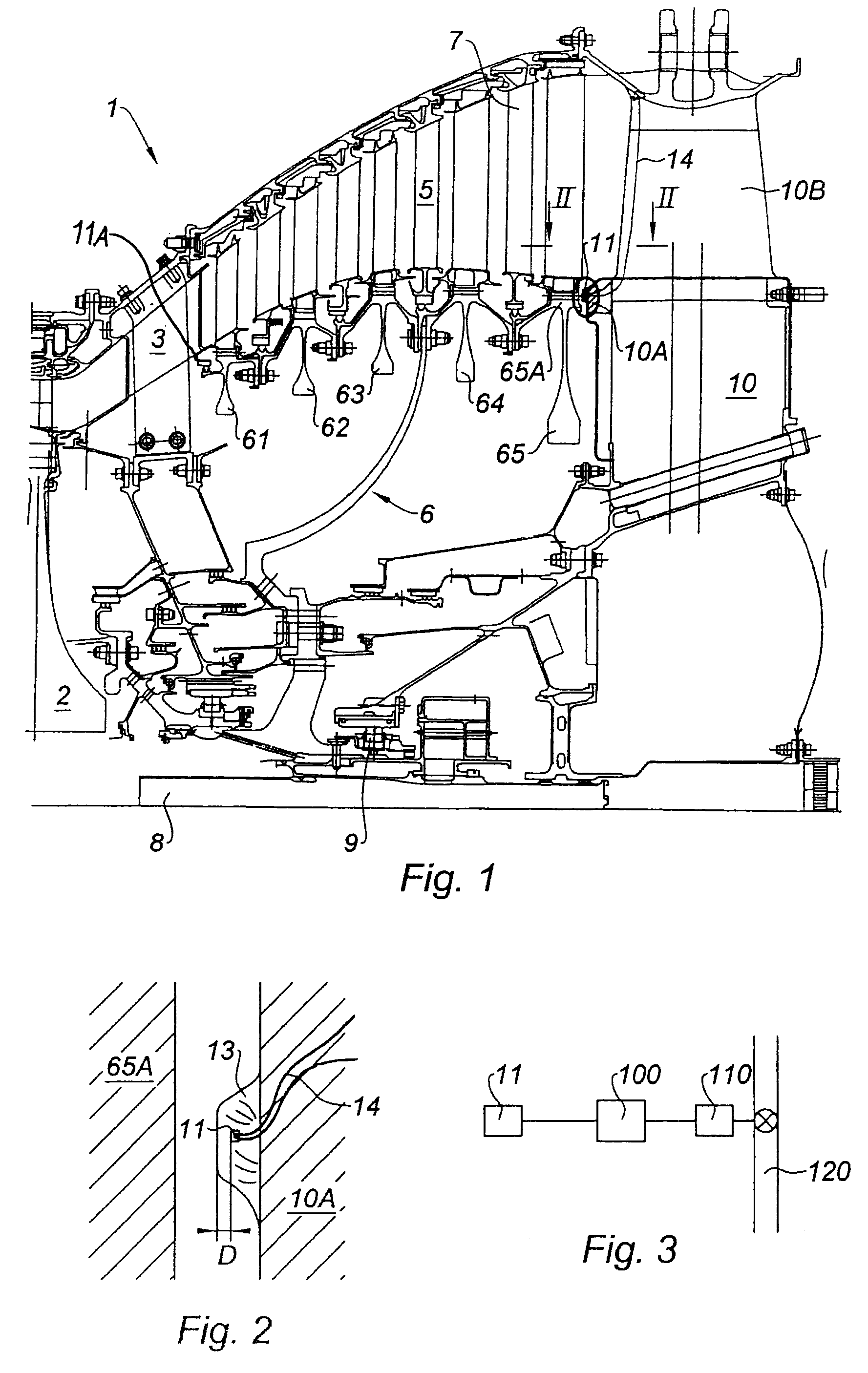
[0016]FIG. 1 shows part of the cross section of a turbine 1 of a gas turbine engine. In a twin-spool bypass engine, the turbine section 1 comprises a high-pressure turbine 2 which receives the hot gases from the combustion chamber, not depicted here. The gases, having passed through the blading of the high-pressure turbine rotor 2 are directed through a fixed nozzle guide vanes assembly 3, onto the low-pressure turbine section 5. This section 5 is made up of a rotor 6 formed, here in the form of a drum, of a collection of several blisks 61 to 65, five of them in this example. The blades, which comprise an airfoil and a root are mounted, generally individually, at the periphery of the disks in housings formed on the rim. Fixed nozzle guide vanes assemblies 7 are inserted between the turbine stages, the purpose of each being to direct the gaseous flow appropriately with respect to the mobile blading downstream. This assembly forms the low-pressure turbine section 5. The turbine rotor ...


PUM


Abstract

A device for detecting breakage of a gas turbine engine shaft and for reducing the rotational speed of the turbine includes a rotor of a turbine or of a first stage turbine driving the shaft. The rotor has a turbine disk with a rim. A stator that the rotor rotates inside or a nozzle guide vanes assembly of the first turbine stage is provided. A temperature sensor is positioned on the stator or on the nozzle guide vanes assembly, immediately downstream of the rim. The sensor is located to sense temperature on a portion of the stator that contacts the rotor, or on a portion of the nozzle guide vanes assembly that contacts the first stage rotor, in the event of shaft breakage. An engine fuel control member connects to the sensor and can interrupt fuel supply to the engine, when the sensor emits a signal above a predetermined threshold.

Description

BACKGROUND OF THE INVENTION[0001]The present invention relates to the field of gas turbine engines, particularly multi-flow turbojet engines, and relates to a system able to detect breakage of a machine shaft so as to shut down the machine in the shortest possible space of time.[0002]In a multi-spool multi-flow turbofan jet engine, the fan is driven by the low-pressure turbine. When the shaft connecting the fan rotor to the turbine rotor breaks, the mechanical load on the turbine is suddenly removed whereas the engine gas flow continues to transmit its energy to the rotor. This then results in a rapid increase in the rotational speed of the rotor which is liable to reach its yield stress and to explode with the ensuing catastrophic consequences.DESCRIPTION OF THE PRIOR ART[0003]Means for slowing the rotor when such an incident occurs have been proposed. The axial displacement of the rotor resulting from breakage of the shaft triggers the operation of mechanisms aimed at dissipating ...

Claims


Application Information

Patent Timeline
Patent Type & Authority Patents(United States)
IPC IPC(8): F02G3/00
CPCF01D21/003F01D21/04F01D21/06F01D21/12F05D2270/3032Y02T50/67Y02T50/671F05D2270/303Y02T50/60
Inventor MONS, CLAUDE MARCEL
Owner SN DETUDE & DE CONSTR DE MOTEURS DAVIATION S N E C M A
Why Eureka
Try Eureka