Vented rotor

a rotor and rotor body technology, applied in the direction of brake elements, brake discs, brake types, etc., can solve the problems of reduced air cooling and non-uniform contact with the brake lining, and achieve enhanced cooling air flow, improved mechanical stability, and improved resistance to heat induced distortion

Inactive Publication Date: 2011-05-03
ROBERT BOSCH CORP +1
View PDF8 Cites 15 Cited by
  • Summary
  • Abstract
  • Description
  • Claims
  • Application Information

AI Technical Summary

Benefits of technology

[0012]An advantage of the present invention is that cooling air flow is enhanced without unduly sacrificing structural integrity.
[0013]Another advantage is that mechanical stability particularly the resistance to heat induced distortion is improved.

Problems solved by technology

Under elevated temperature usage the difference in thermal stress between the inboard and outboard brake plate causes a coning effect that distorts the brake plate surfaces resulting in non-uniform contact with the brake linings.
The detriment to implementing this approach is that air cooling is reduced by closing off the ability of the vanes between the brake plates to dissipate the heat.

Method used


Image

  • Vented rotor
  • Vented rotor
  • Vented rotor

Examples


Embodiment Construction

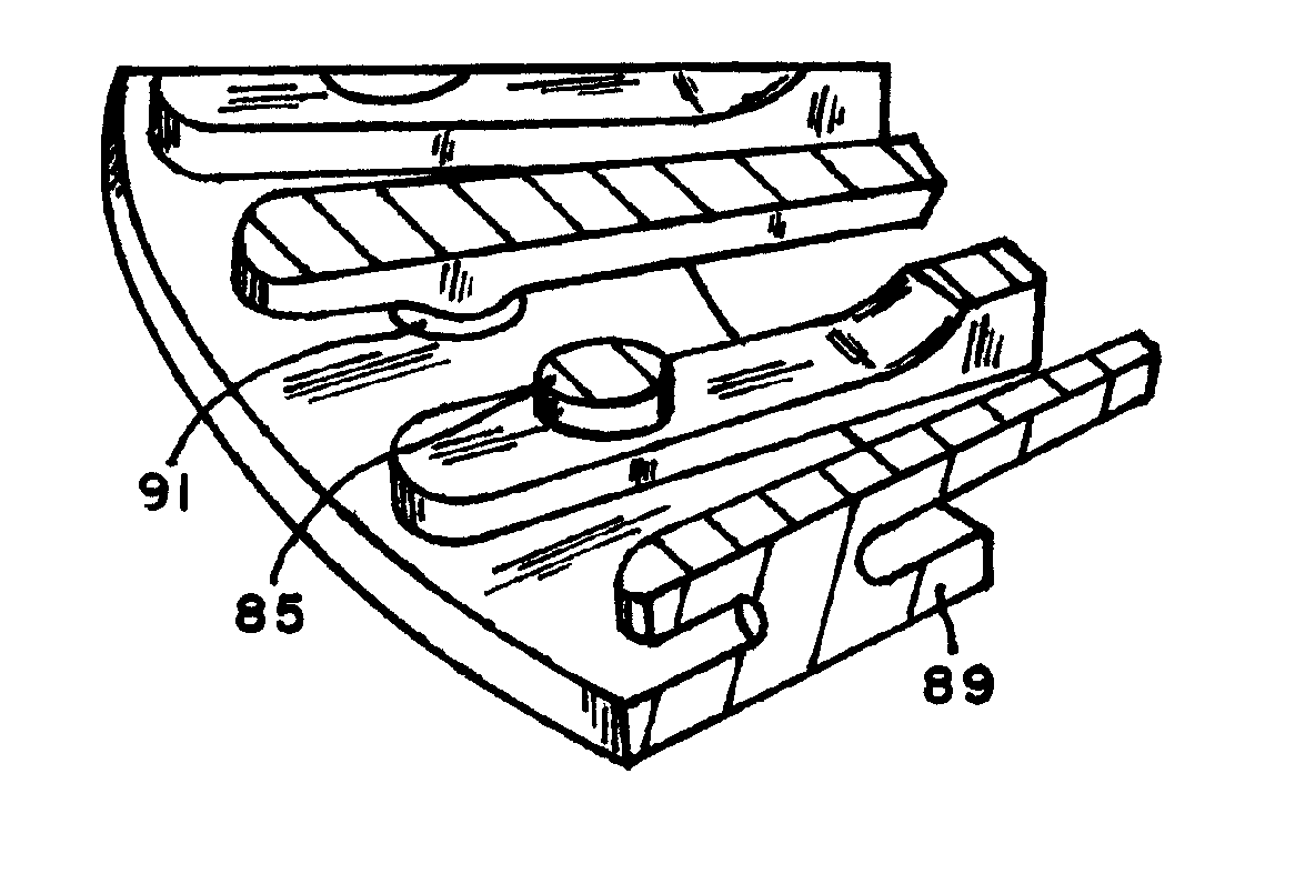
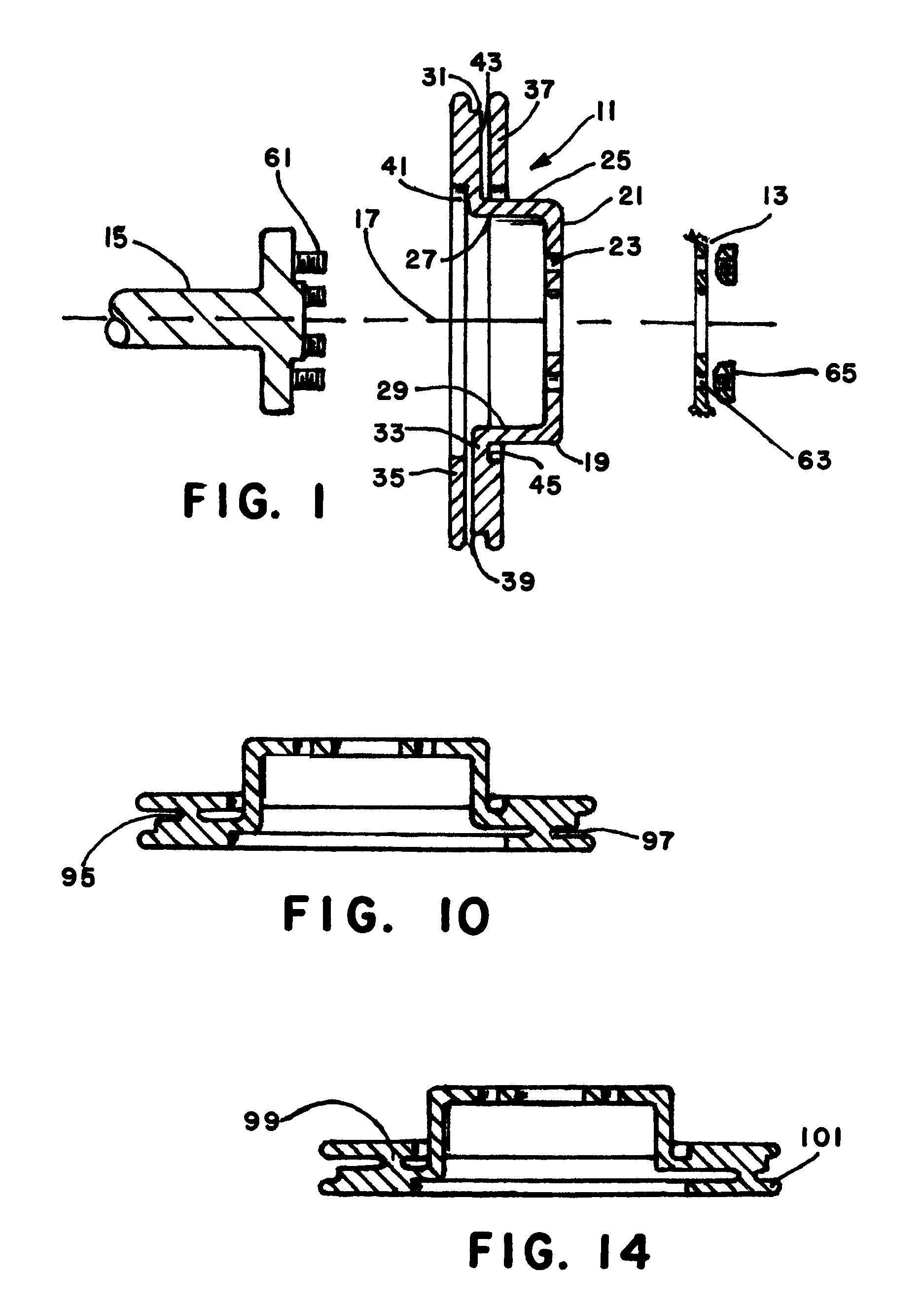
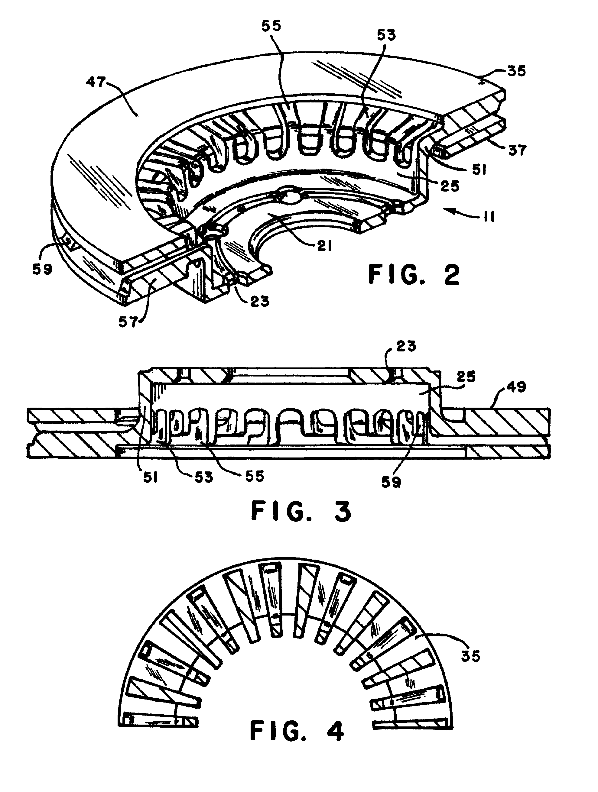
[0029]Referring now to the drawings and particularly to FIG. 1, there is shown, in exploded cross-section, a simplified illustration of a vehicle axle 15, brake component 11 and a portion of a vehicle wheel 13. The wheel 13 and brake component 11 are assembled to the axle 15 by passing the wheel bolts such as 61 through brake component openings such as 23 and corresponding wheel openings 63 to thereafter receive lug nuts such as 65 as is conventional. FIG. 1 is simplified showing only two lug nuts 65, however it is common to employ four to six or more wheel bolts and lug nuts. Brake component 11 is a rotor for a disk brake system having inboard 47 and outboard 49 braking surfaces to which spanning rotationally fixed brake friction pads (not shown) are selectively applied to brake vehicle wheel rotation. Rotor 11 includes a hub or hat portion 19 having a central plate 21 with a plurality of threaded fastener openings 23 for attaching the component to vehicle wheel 13 and a generally ...


PUM


Abstract

A disc brake rotor having a central hat portion for coupling a rotor to a vehicle wheel for rotation about a central axis, an inboard brakeplate for receiving a first friction surface and an outboard brakeplate for receiving a second friction surface. A plurality of L-shaped rib members extends from the hat for coupling the inboard brakeplate to the hat and a second plurality of L-shaped members radially extend from the hat for coupling the outboard brakeplate to the hat. First plurality of ribs is longer than the second plurality of ribs. The second set L-shaped members is located intermediate of the edges of the inboard and outboard pluralities to enhance the heat transfer of the braking operation.

Description

[0001]The present invention relates to vehicle braking systems of the disc variety, and more particularly to a disc brake rotor having improved performance features including enhanced heat transfer capability.BACKGROUND OF THE INVENTION[0002]Conventional vehicle disc brakes employ a rotor fixed to and rotatable with a vehicle wheel having a pair of planar annular friction faces for receiving the pads of a spanning caliper mechanism. The rotor may be formed with a central hub or hat section for attachment to a wheel and two radially extending plates interconnected by ribs to allow airflow radially between the plates to better dissipate the heat generated during braking.[0003]The conventional brake rotor design connects the braking surfaces to the hat section of the rotor via the outboard brake plate. Under elevated temperature usage the difference in thermal stress between the inboard and outboard brake plate causes a coning effect that distorts the brake plate surfaces resulting in ...

Claims


Application Information

Patent Timeline
Patent Type & Authority Patents(United States)
IPC IPC(8): F16D65/10
CPCF16D65/123F16D65/128F16D65/847F16D2065/788F16D2065/1316F16D2065/1392
Inventor BLACK, DAVID REED
Owner ROBERT BOSCH CORP
Why Eureka
Try Eureka