
Brushless DC motor with reduced current ripple

a brushless dc motor and current ripple technology, applied in the direction of motor/generator/converter stopper, dynamo-electric converter control, pulse technique, etc., can solve the problem of reducing motor efficiency, reducing motor efficiency, and reducing the efficiency of motors, so as to achieve uniform summed or resultant current, enhance motor efficiency and life, and reduce the effect of current rippl

Inactive Publication Date: 2011-05-10
LTI HLDG INC
View PDF29 Cites 18 Cited by
  • Summary
  • Abstract
  • Description
  • Claims
  • Application Information

AI Technical Summary

Benefits of technology

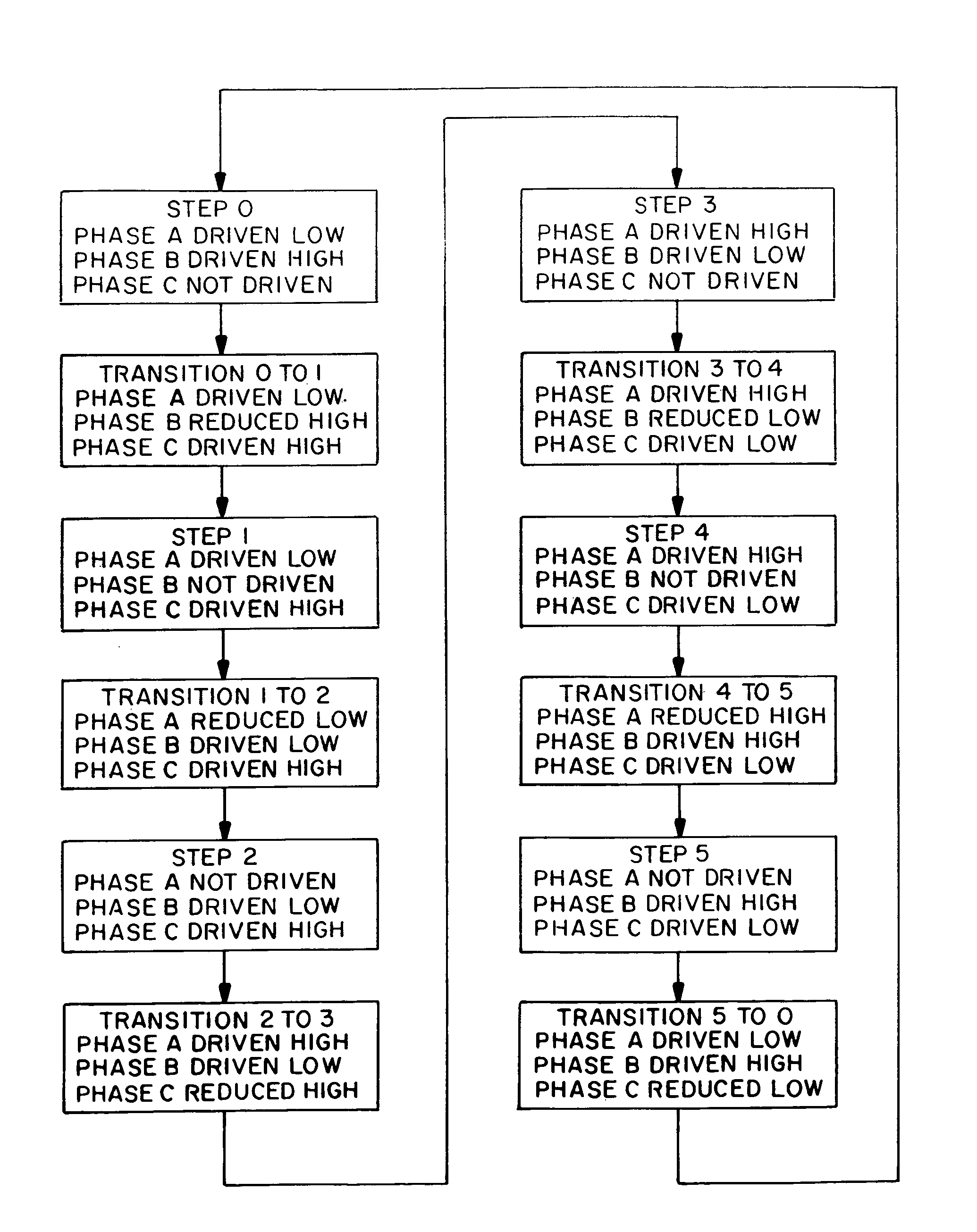
[0023]Further in connection with three phase motors, the preferred commutation cycle consists of six primary steps alternating with six transitional steps over 360 degrees of electrical rotation. Depending on the motor design, each mechanical rotation of the rotor may be equivalent to one electrical rotation or an integral number of electrical rotations. In either event, each pair including a primary step and its adjacent transitional step has an angular dimension of sixty degrees. The transitional steps have an angular dimension of at most twenty degrees, and more preferably have an angular dimension of about ten degrees. The smaller transitional steps provide sufficient current smoothing while ensuring that each phase of the motor remains inactive for a sufficient time to enable use of the back EMF signal to determine rotor position.
[0024]In accordance with the present invention, a trapezoidally commutated motor can be operated to undergo smoother transitions and with the more uniform summed or resultant current associated with sinusoidally driven motors. This enhances motor efficiency and life, and allows for the use of trapezoidally driven motors in applications that traditionally would require sinusoidal drives.

Problems solved by technology

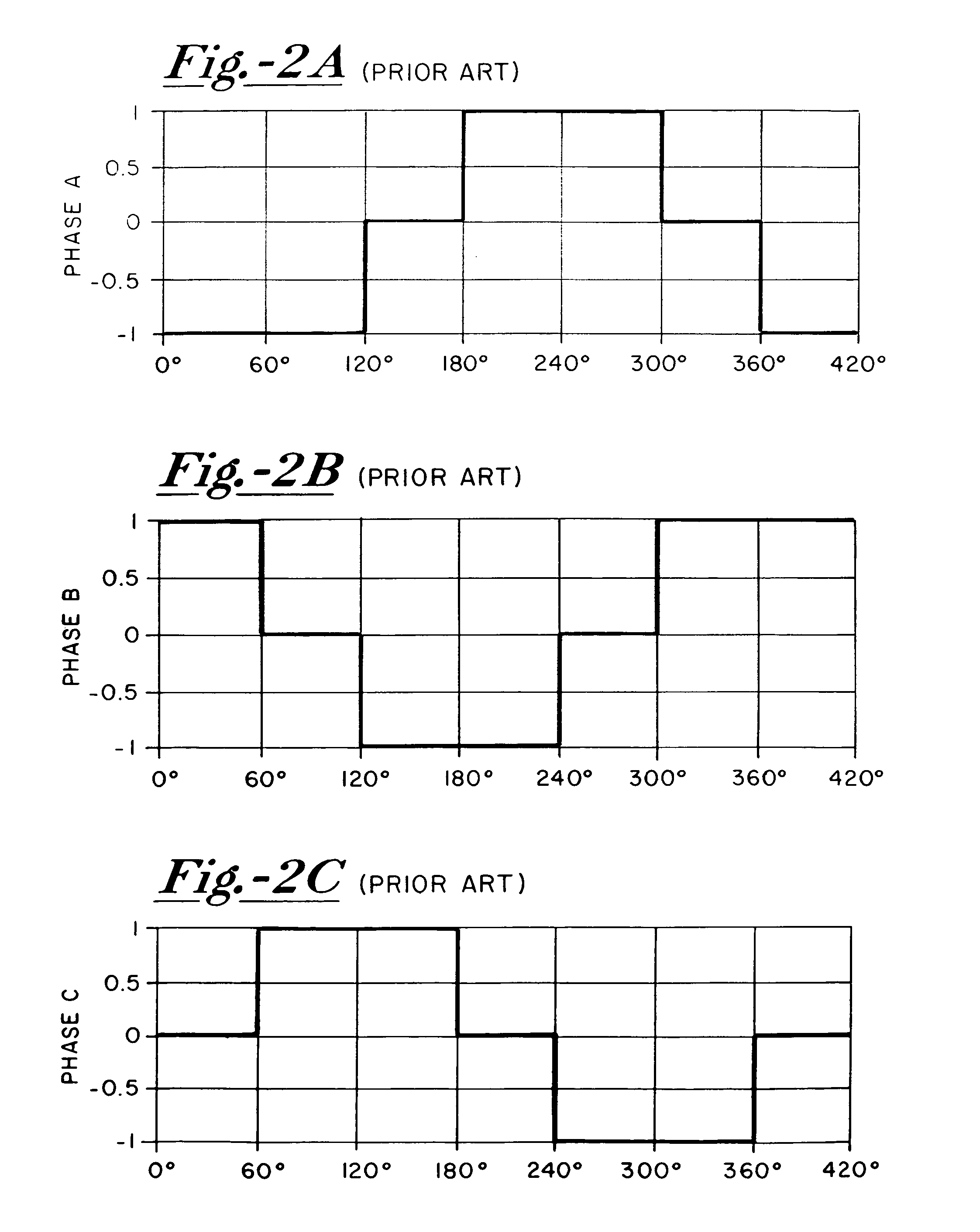
The repeating fluctuations, known as commutation current ripple, result in a corresponding commutation torque ripple that is undesirable because it increases motor noise and reduces motor efficiency.
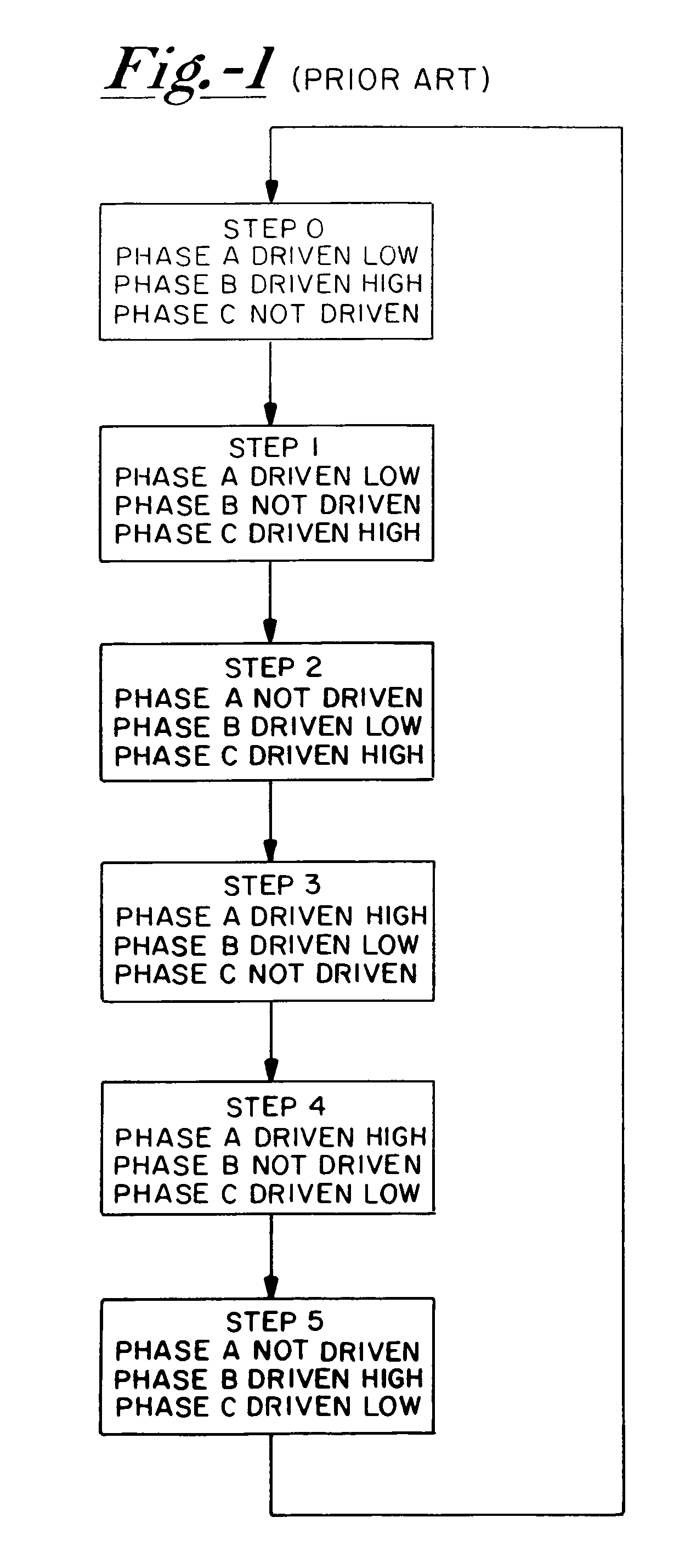
While this is a tolerable result in many applications, more demanding environments require the more complex and more costly sinusoidal commutation.

Method used


Image

  • Brushless DC motor with reduced current ripple
  • Brushless DC motor with reduced current ripple
  • Brushless DC motor with reduced current ripple

Examples


Embodiment Construction

[0040]With further reference to the drawings, FIG. 5 shows a system 16 for coupling a 3-phase brushless DC motor to a DC power supply 18. System 16 includes a commutation circuit or driver 20 having input terminals 22 and 23 coupled respectively to a high voltage line 24 and low voltage line 26 of the power supply. Driver 20 has several output terminals 28, 30 and 32 coupled to the motor. The motor includes a rotor 34 surrounded by a stator 36 and supported for rotation relative to the stator through selective driving of stator windings 38, 40 and 42 which represent angularly separated phases A, B, and C of the motor. Driver output terminals 28, 30 and 32 are coupled respectively to stator windings 38, 40 and 42.

[0041]System 16 further includes a controller 44, preferably a microprocessor, for controlling driver 20 to selectively and alternatively apply the high voltage and the low voltage individually to stator windings 38, 40 and 42. Controller 44 further is coupled to output term...


PUM


Abstract

A commutation circuit for driving a brushless DC motor is controlled according to a commutation cycle composed of alternating primary steps and transitional steps. The commutation circuit includes pairs of field effect transistors coupled in series between the high voltage and low voltage terminals of a DC power supply. Output terminals between each pair of transistors are individually coupled to the phases of a DC motor. A controller operates the commutation circuit to selectively set the phases at active and inactive states. The controller further employs a plurality of voltage control functions individually associated with the motor phases to selectively modulate the voltage applied to one of the phases during the active states, to provide transitional steps in the commutation cycle during which the applied voltage is modulated to reduce its magnitude with respect to the high voltage or the low voltage.

Description

BACKGROUND OF THE INVENTION[0001]The present invention relates to electrically commutated motors, and more particularly to controllers and drivers for trapezoidally commutated motors.[0002]Brushless electronically commutated motors have been utilized increasingly in lieu of brushed DC motors in numerous applications, primarily for their advantages of lower cost, higher efficiency, and longer useful life. Electronically commutated motors and drivers generally are provided in two types: sinusoidally commutated motors and trapezoidally commutated motors.[0003]Sinusoidally commutated motors, also known as permanent magnet AC synchronous motors, have a back EMF (electromotive force) waveform similar to a sine wave. In a three-phase motor, all phases are driven simultaneously at different voltages that vary substantially sinusoidally. Separate position sensors, e.g. Hall effect sensors, are required to provide the necessary rotor position information to the electronic drive.[0004]Trapezoi...

Claims


Application Information

Patent Timeline
Patent Type & Authority Patents(United States)
IPC IPC(8): H03K5/00
CPCH02P6/002H02P6/16H02P2209/07H02P6/28
Inventor BROWN, ROBERT G.
Owner LTI HLDG INC
Learn More