

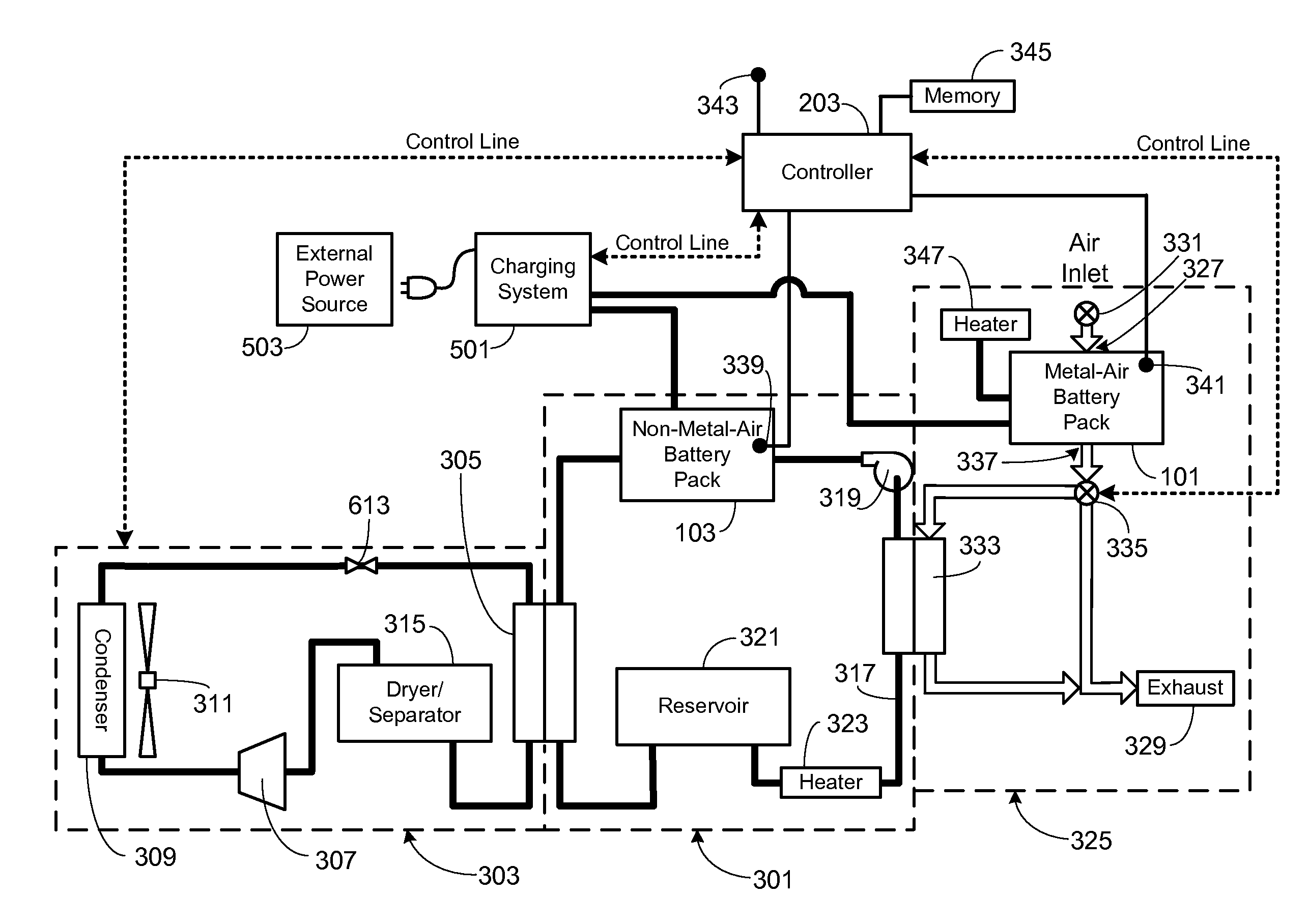
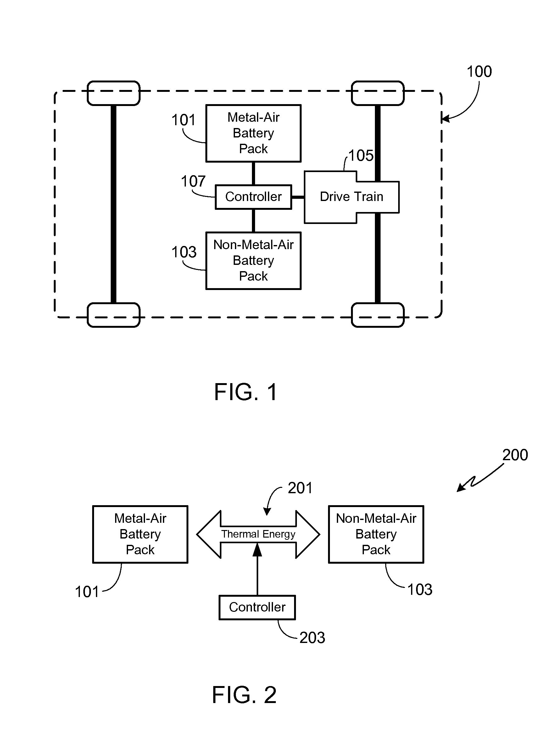
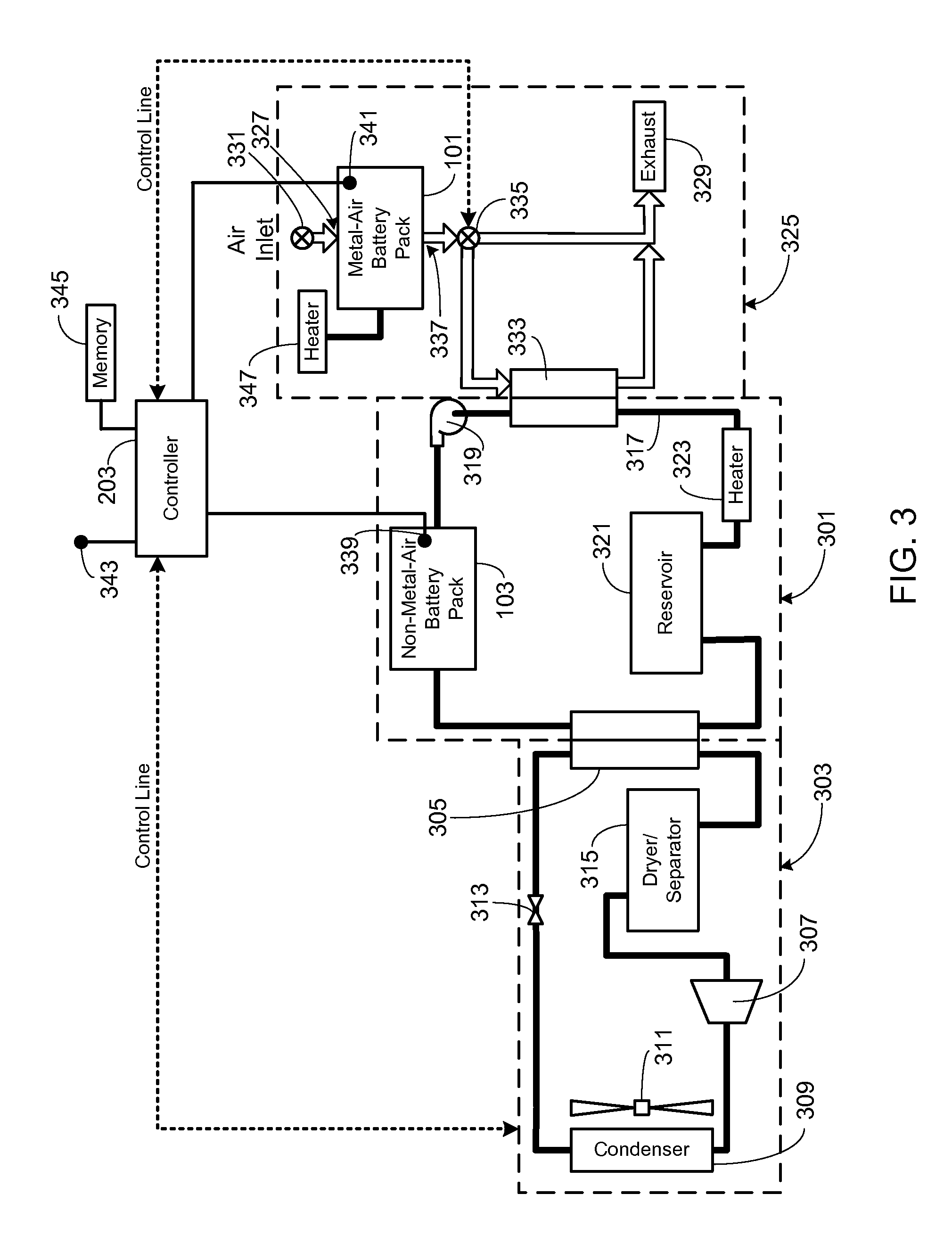
Thermal energy transfer system for a power source utilizing both metal-air and non-metal-air battery packs
a technology of metal air and battery pack, applied in the field of batteries, can solve the problem of metal air cell discharge ra
- Summary
- Abstract
- Description
- Claims
- Application Information
AI Technical Summary
Benefits of technology
Problems solved by technology
Method used
Image

Examples
Embodiment Construction
[0017]In the following text, the terms “battery”, “cell”, and “battery cell” may be used interchangeably. The term “battery pack” as used herein refers to multiple individual batteries contained within a single piece or multi-piece housing, the individual batteries electrically interconnected to achieve the desired voltage and capacity for a particular application. The terms “battery” and “battery system” may be used interchangeably and as used herein refer to an electrical energy storage system that has the capability to be charged and discharged such as a battery or battery pack. The term “electric vehicle” as used herein refers to either an all-electric vehicle, also referred to as an EV, plug-in hybrid vehicles, also referred to as a PHEV, or a hybrid vehicle (HEV), a hybrid vehicle utilizing multiple propulsion sources one of which is an electric drive system. It should be understood that identical element symbols used on multiple figures refer to the same component, or compone...
PUM
| Property | Measurement | Unit |
|---|---|---|
| reaction rate | aaaaa | aaaaa |
| temperature | aaaaa | aaaaa |
| temperature | aaaaa | aaaaa |
Abstract
Description
Claims
Application Information