Battery-powered occupancy sensor

a battery-powered occupancy sensor and occupancy sensor technology, applied in the direction of electric signalling details, instruments, containers, etc., can solve the problems of increasing the likelihood that the load control device may not detect the presence of a user, and the control system requires advanced system components and configuration procedures in order to operate properly

Inactive Publication Date: 2011-05-10
LUTRON TECH CO LLC
View PDF70 Cites 198 Cited by
  • Summary
  • Abstract
  • Description
  • Claims
  • Application Information

AI Technical Summary

Benefits of technology

[0008]According to an embodiment of the present invention, a battery-operated occupancy sensor for sensing the presence or absence of an occupant in an area comprises a controller circuit, an occupancy detector circuit having an output coupled to the controller for delivering occupancy or vacancy information to the controller, an RF transmitter circuit responsive to the controller to transmit an RF signal related to the output of the occupancy detector circuit, a first battery connected to the occupancy detector circuit for energizing the circuits thereof, and a second battery connected to the controller and the RF transmitter for energizing their respective circuits, whereby electronic noise produced by the controller and the RF transmitter is isolated from the occupancy detector circuit without excessive electronic filtering.

Problems solved by technology

However, since the wall-mounted load control devices are mounted to a wall in a standard electrical wallbox (i.e., replacing a standard light switch), the detection of energy by the PIR detector may be hindered due to the direction that the load control device is facing and by obstacles in the space, thus increasing the likelihood that the load control device may not detect the presence of a user.
However, these prior art lighting control systems require advanced system components and configuration procedures in order to operate properly.

Method used


Image

  • Battery-powered occupancy sensor
  • Battery-powered occupancy sensor
  • Battery-powered occupancy sensor

Examples


first embodiment

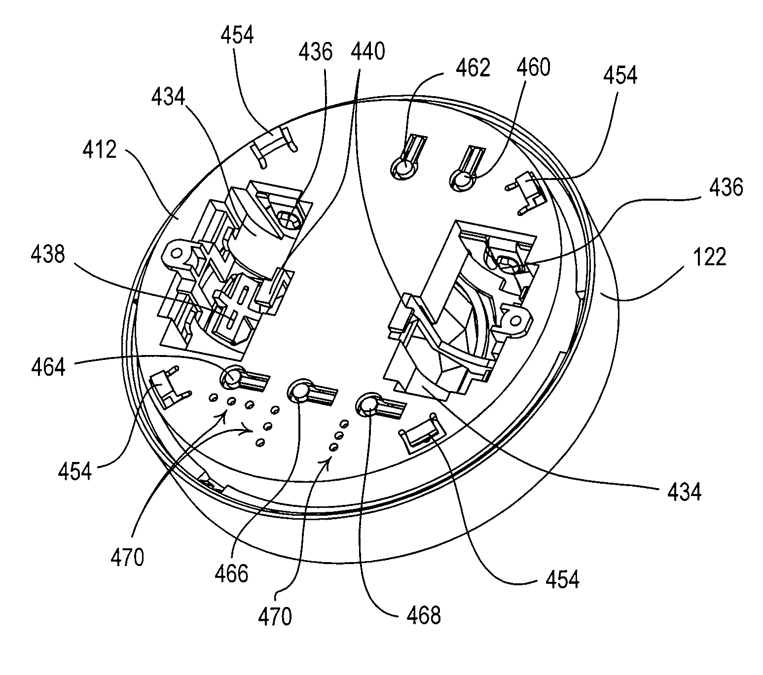
[0065]According to the present invention, the occupancy sensors 120 are each operable to store in a memory 240 the values of the various operating characteristics of the lighting control system 100, e.g., the occupancy voltage threshold, the ambient light level threshold, and the occupancy sensor timeout period TTIMEOUT. The memory 240 may be implemented as an external integrated circuit (IC) or as an internal circuit of the controller 230. To adjust the values of the operating characteristics, the user must access the occupancy sensor 120 to actuate the actuators 236. The occupancy sensors 120 use the operating characteristics to change between the occupied state and the vacant state as will be described in greater detail below. The occupancy sensors 120 also store the serial number in the memory 240. The serial number may be programmed into the memory 240, for example, during manufacture of the occupancy sensor 120.

[0066]The remote occupancy sensor 120 further comprises an RF tran...

second embodiment

[0100]According to the present invention, the dimmer switch 110 is operable to store in the memory 216 the values of the various operating characteristics of the lighting control system 100, e.g., the occupancy voltage threshold, the ambient light level threshold, and the occupancy sensor timeout period TTIMEOUT. The dimmer switch 110 may provide, for example, an advanced programming mode, such that the values of the operating characteristics may be adjusted in response to actuations of the toggle actuator 114 and the intensity adjustment actuator 116. An advanced programming mode is described in greater detail in U.S. Pat. No. 7,190,125, issued Mar. 13, 2007, entitled PROGRAMMABLE WALLBOX DIMMER, the entire disclosure of which is hereby incorporated by reference. Since the user does not need to access the occupancy sensors 120 (which may be mounted to a ceiling) to adjust the operating characteristics, the use of the toggle actuator 114 and the intensity adjustment actuator 116 of ...

third embodiment

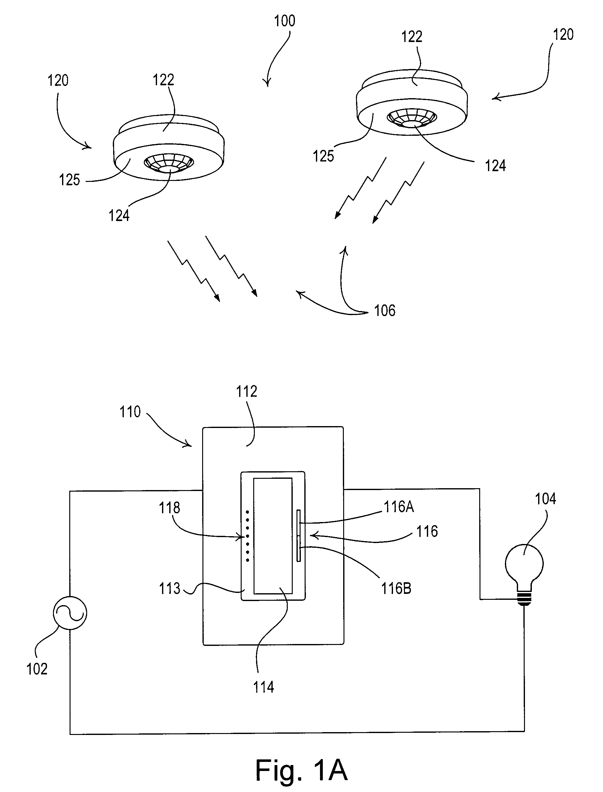
[0110]FIG. 17A is a simplified block diagram of a lighting control system 100′ having a dimmer switch 110′ according to the present invention. The lighting control system 100′ may additionally comprise one or more remote controls 130. The remote control 130 comprises a plurality of actuators: an on button 132, an off button 134, a raise button 136, a lower button 138, and a preset button 140 (for recalling a preset lighting intensity stored in the memory 216 of the dimmer switch 110′). Alternatively, the remote control 130 could comprises a plurality of preset buttons. The remote control 130 transmits digital messages via the RF signals 106 to the dimmer switch 110′ in response to actuations of any of the actuators. The dimmer switch 110′ is responsive to digital messages containing the serial number of the remote control 130 to which the dimmer switch is associated. The dimmer switch 110′ is operable to turn on and to turn off the lighting load 104 in response to an actuation of th...


PUM


Abstract

A battery-powered occupancy sensor for detecting an occupancy condition in a space comprises first and second batteries, an occupancy detector circuit, a controller, and a wireless transmitter for transmitting a first wireless signal in response to the occupancy detector circuit detecting the occupancy condition in the space. The controller and the wireless transmitter are powered by the first battery, while only the occupancy detector circuit is powered by the second battery, such that the occupancy detector circuit is isolated from noise generated by the controller and the wireless transmitter. The occupancy detector circuit draws a current having a magnitude of approximately 5 microamps or less from the second battery. The occupancy sensor transmits a second wireless signal is response to determining that the voltage of one of the batteries has dropped too low.

Description

BACKGROUND OF THE INVENTION[0001]1. Field of the Invention[0002]The present invention relates to occupancy and vacancy sensors for detecting an occupancy or a vacancy in a space, and more particularly, to a wireless load control system including a plurality of battery-powered occupancy or vacancy sensors for detecting an occupancy or a vacancy in a space, and a load control device for controlling the amount of power delivered to an electrical load in response to the occupancy or vacancy sensors.[0003]2. Description of the Related Art[0004]Occupancy and vacancy sensors are often used to detect occupancy and / or vacancy conditions in a space in order to control an electrical load, such as, for example, a lighting load. An occupancy sensor typically operates to turn on the lighting load when the occupancy sensor detects the presence of a user in the space (i.e., an occupancy event) and then to turn off the lighting load when the occupancy sensor detects that the user has left the space ...

Claims


Application Information

Patent Timeline
Patent Type & Authority Patents(United States)
IPC IPC(8): G08B1/08G08B13/00G08B23/00B65D85/00
CPCG08B29/24H05B39/086H05B37/0227H05B47/11H05B47/13Y02B20/40
Inventor STEINER, JAMES P.SCHMALZ, ANDREW PETERSLOAN, GREG EDWARD
Owner LUTRON TECH CO LLC
Why Eureka
Try Eureka