
Laser optical device and control method of actuator

a technology of laser light source and optical device, which is applied in the direction of program control, instruments, television systems, etc., can solve the problems of large heat generation effect caused by laser light source, inability to correct, and relatively difficult to achieve a high yield rate in the manufacture of such laser optical device, etc., to achieve accurate propagation of information and high performance

Inactive Publication Date: 2011-05-10
KONICA MINOLTA OPTO
View PDF31 Cites 1 Cited by
  • Summary
  • Abstract
  • Description
  • Claims
  • Application Information

AI Technical Summary

Benefits of technology

[0011]The invention has been achieved in view of the above problems, and an object of the present invention is to provide a laser optical device capable of accurate propagation of information and maintaining high performance, in the laser optical device to position the laser signal light condensed and modulated by the information to the incident surface of the optical fiber.

Problems solved by technology

However, even if the laser optical device is configured by adhesive so that the relative position of the parts is accurately aligned and firmly fixed is such way, the following problems remain.
Also, it is considered that achieving of a high yield rate in manufacturing of such laser optical device is relatively difficult.
Second, in case the performance is deteriorated with time, correction is impossible.
In case a laser light source is located particularly near the optical parts, an effect caused by heat generated by the laser light source is large.
However, the optical communication device disclosed in Patent Document 1 does not have suggestion to cope with accurate propagation of the information without being affected by the change of the intensity, considering the change of the intensity of the laser signal light caused by wobbling.
The optical communication device disclosed in the Patent Document 1 does not have such actuator as above having high resolution capable of highly accurate positioning control and it is thought that sub-micron order positioning controls is difficult to be implemented.
Therefore, a S / N rate is deteriorated and detection of change of the intensity of the laser light is difficult.

Method used


Image

  • Laser optical device and control method of actuator
  • Laser optical device and control method of actuator
  • Laser optical device and control method of actuator

Examples


embodiment 1

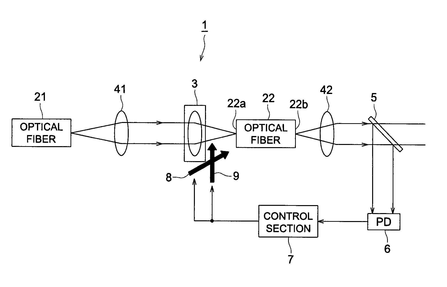
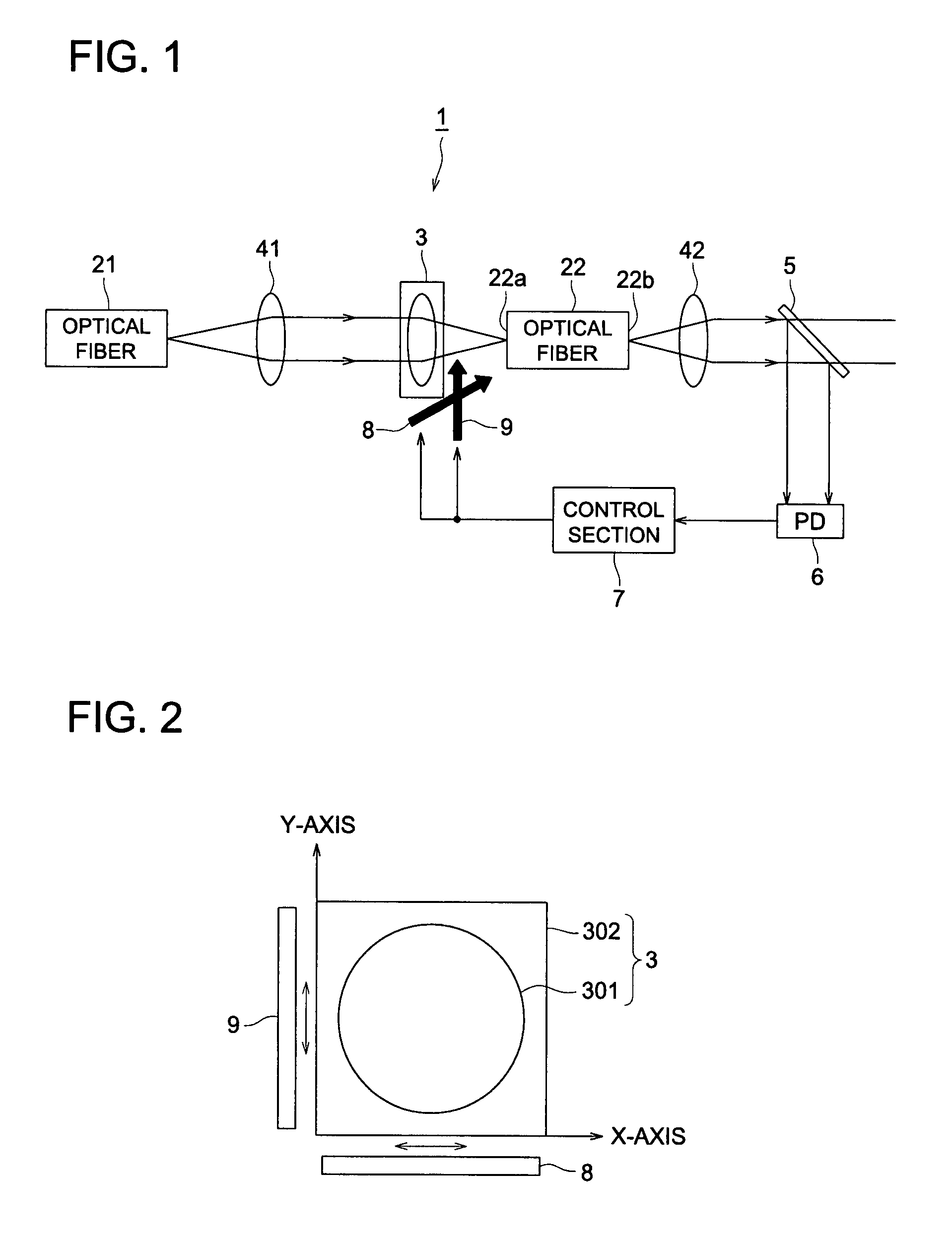
[0031]First, a structure of a laser optical device is described with reference to FIG. 1. FIG. 1 is a view showing an outline of an entire structure of laser optical device 1.

[0032]As FIG. 1 shows, laser optical device 1 has optical fibers 21 and 22, light condensing optical unit 3, collimater lenses 41 and 42, half mirror 5, photo diode 6, control section 7, and actuators 8 and 9.

[0033]Optical fibers 21 and 22, light condensing optical unit 3, collimater lenses 41 and 42 are disposed in a common optical axis and laser light emitted from optical fiber 21 is condensed towards incident surface 22a of optical fiber 22 through light condensing optical unit 3. Thus optical fibers 21 and 22 respectively function as a laser emitting section and a laser receiving section in the laser optical device related to the present invention. Meanwhile, as the laser emitting section, optical fiber 21 can be substituted by LD also, as the laser receiving section, optical fiber 22 can be substituted by ...

embodiment 2

[0067]Next embodiment 2 of laser optical device 1 is explained. Since a main structure of embodiment 2 is the same as that of the aforesaid embodiment 1, detailed description is omitted and wobbling operation in the X-axis having a different sequence from that of embodiment 1 and a timing of dithering operation in the Y-direction is described.

[0068]In the laser optical device 1 of embodiment 1, while the wobbling operations in the X-axis and Y-axis directions are implemented alternatively in sequence by changing them over, in laser optical device 1 of embodiment 2, wobbling operations in the X-axis direction and Y-axis direction are implemented simultaneously by satisfying a specific relation in wobbling operation frequency.

[0069]In practice, it is explained with reference to FIG. 11. FIG. 11 is a time chart of other example of wobbling operation.

[0070]Here, when a frequency of wobbling operation in the X-axis is f1 and that of in the Y-axis is f2, values to satisfy the following fo...


PUM


Abstract

A laser optical device, having: a laser light emitting section to emit laser signal light modulated by information; a laser light receiving section to receive the laser signal light emitted from the laser light emitting section; a light condensing optical unit to conduct the laser signal light emitted from the laser light emitting section to the laser light receiving section; an actuator to move the light condensing optical unit; a light intensity detecting section to detect an intensity of the laser signal light conducted to the laser light receiving section; and a control section to control drive of the actuator so as to align the laser signal light conducted by the light condensing optical unit to the laser light receiving section; wherein the control section drives the actuator in a predetermined period which synchronizes with a predetermined signal included in the laser signal light.

Description

[0001]This application is based on Japanese Patent Applications No. 2006-199202 filed on Jul. 21, 2006, and No. 2006-223160 filed on Aug. 18, 2006 in Japanese Patent Office, the entire content of which is hereby incorporated by references.BACKGROUND OF THE INVENTION[0002]The present invention relates to a laser optical device to align a laser beam to an incident surface of an optical fiber and an operating method of an actuator.[0003]The laser optical device is to emit light by a semiconductor laser element (hereinafter called LD), propagates a laser signal light modulated by information to an optical fiber or propagates a laser signal light emitted from a optical fiber to the other optical fiber and is configured with optical parts such as LD, a condenser lens to condense the laser signal light form LD or the optical fiber and the optical fiber.[0004]In such laser optical device, LD and the condenser lens have to be aligned with high accuracy in respect to the optical fiber having ...

Claims


Application Information

Patent Timeline
Patent Type & Authority Patents(United States)
IPC IPC(8): G02B6/26G02B7/02H04N5/225H04B10/00
CPCG02B6/4225G02B6/4227G02B6/4226
Inventor SHIBATANI, KAZUHIROHATA, YOSHIAKIKANEZAWA, SHINGO
Owner KONICA MINOLTA OPTO
Learn More