Method for changing the direction of travel of a watercraft and apparatus therefor

a technology of watercraft and direction of travel, which is applied in the direction of steering components, floating buildings, vessel safety, etc., can solve the problems of reducing affecting the safety of the vessel, and the inability to quickly steer a large vessel traveling at high speed, so as to reduce the collateral damage of the vessel

Inactive Publication Date: 2011-05-24
SINGAPORE TECH DYNAMICS PTE
View PDF9 Cites 13 Cited by
  • Summary
  • Abstract
  • Description
  • Claims
  • Application Information

AI Technical Summary

Benefits of technology

[0018]In another form of the present invention, the thrust vectoring waterjets in the watercraft are activated to assist in the steering of the errant vessel or keeping the watercraft close to the errant vessel's hull. It can also help to generate the hydrodynamic side thrust to yaw the vessel by impinging the waterjets at the flap.
[0025]is designed for modular deployment. Depending on the tonnage, maximum cruise speed and the desired turning radius of the vessel to be engaged, one or more of such watercraft can be deployed to achieve the mission most effectively. As such, these watercrafts can effectively engage vessel with 300,000 ton or more with maximum cruise speed of 15 to 20 knots.
[0026]minimizes and reduces collateral damage to the vessel and environmental hazard due to the potential pollution or blockage of the fairway by sinking the vessel containing flammable goods.

Problems solved by technology

Just as aircrafts have been used as a weapon or missile to attack or destroy buildings or other large structures, it is envisagable that ships, tankers or watercrafts, harbours, port installations and the like can be destroyed or seriously damaged by the use of tankers or large ships as missiles of attack.
This method is disadvantageous in that it is unable to quickly steer a large vessel that is traveling at high speed.
The towing cable may snap.
In addition it may not be possible to connect the cable to the large vessel, as access to the vessel would be denied.
This system of capturing and / or stopping the vessel is only suitable where the attacking vessel is a small vessel.
It is not suitable for arresting large shipping vessels.
These methods and the apparatus used are not suitable when the errant sailing vessel is traveling fast and with a large momentum.

Method used


Image

  • Method for changing the direction of travel of a watercraft and apparatus therefor
  • Method for changing the direction of travel of a watercraft and apparatus therefor
  • Method for changing the direction of travel of a watercraft and apparatus therefor

Examples


Embodiment Construction

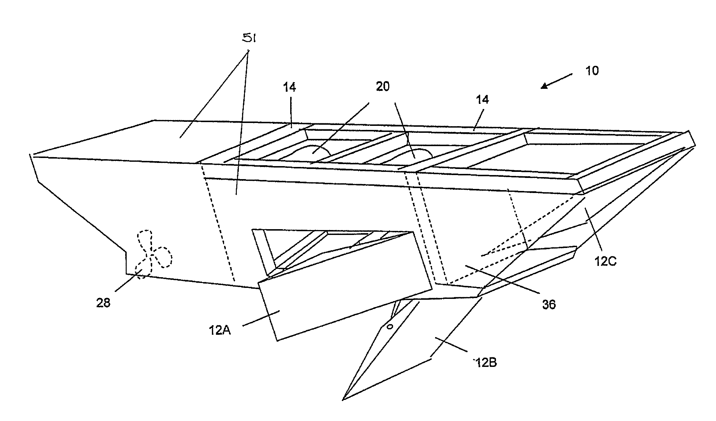
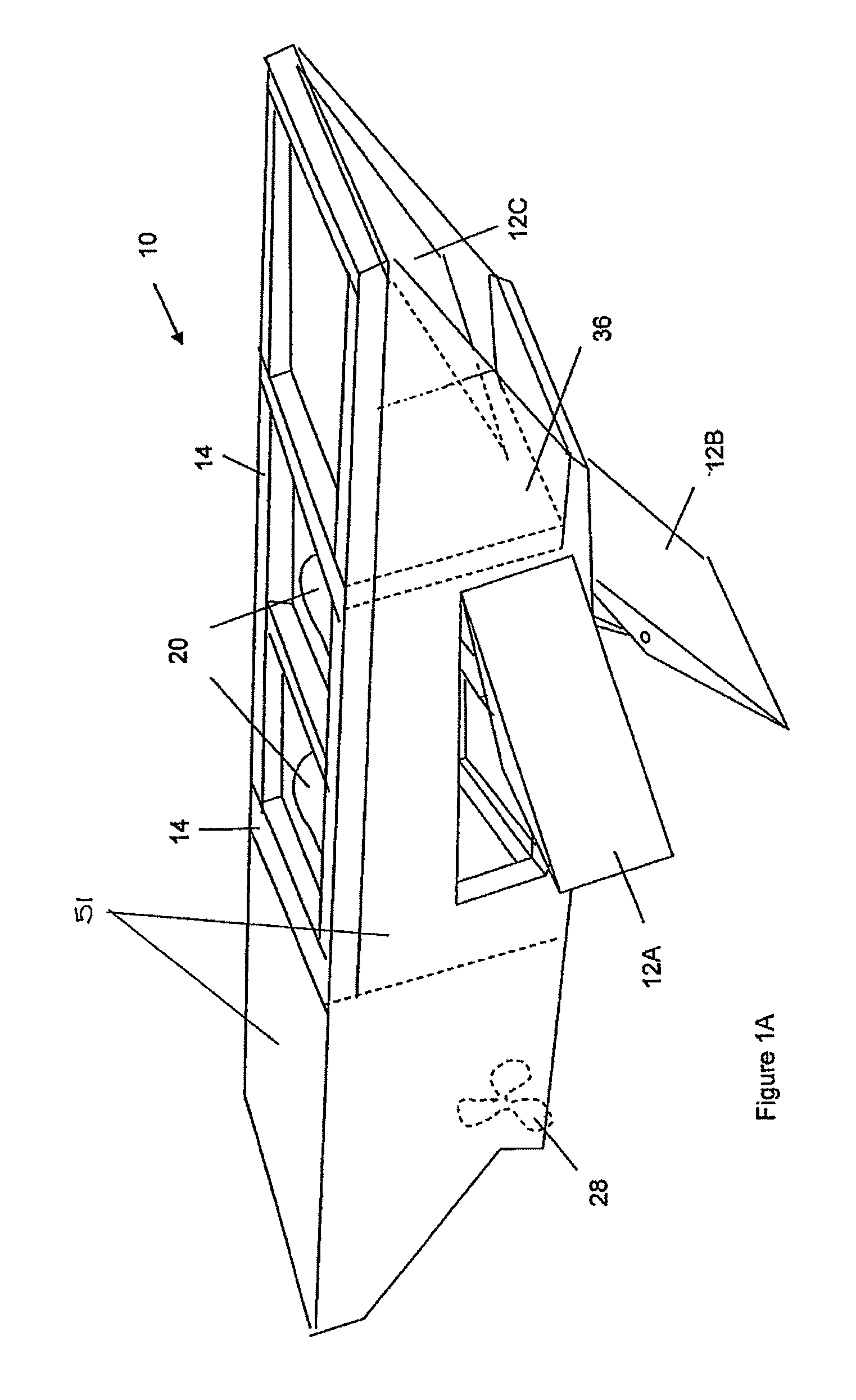
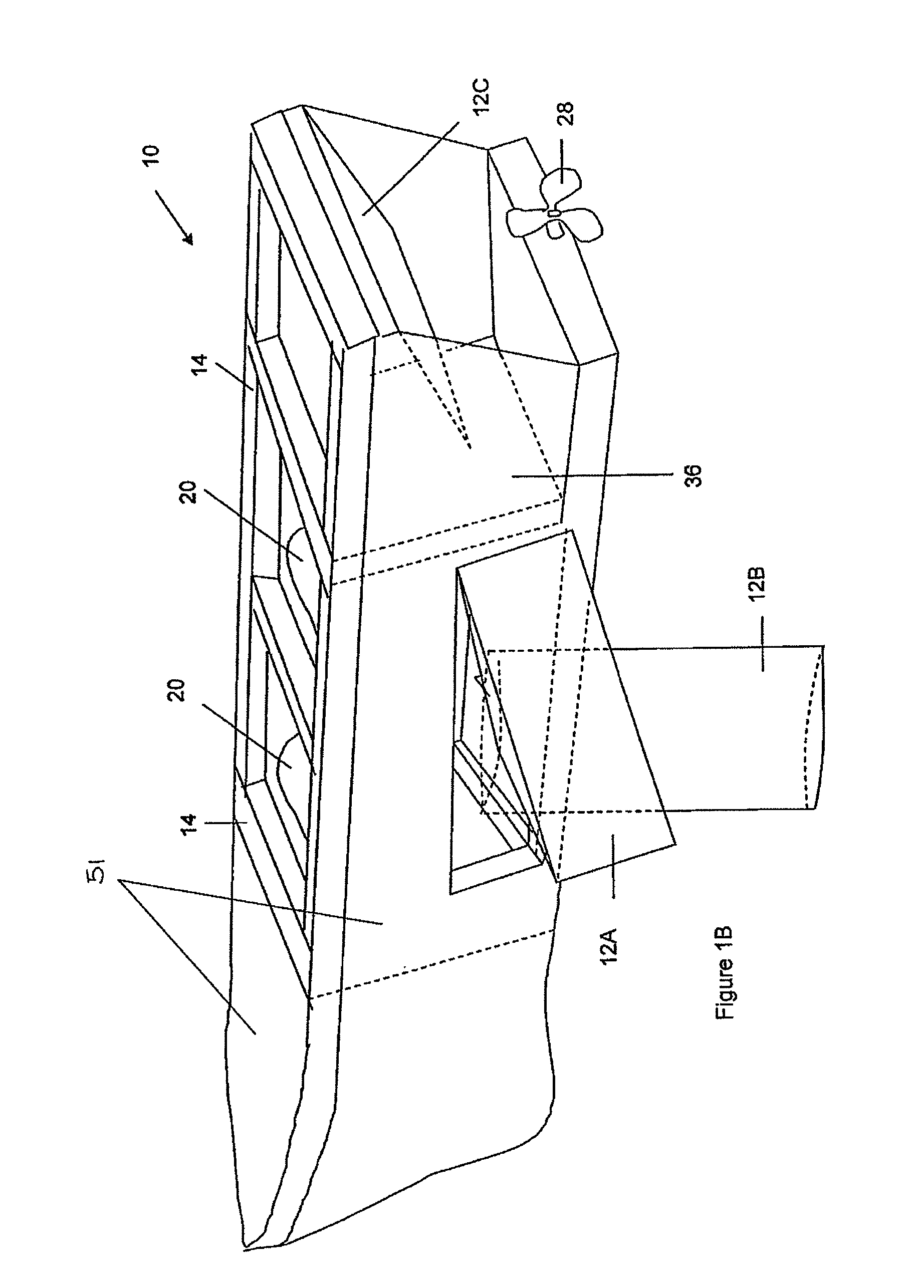
[0043]The invention relates to a system comprising a watercraft that is collectively (a) designed to be operated by man or unmanned control (b) for high maneuverability and speed to enable quick interception of a large vessel (c) that can be securely fastened to the sides of the vessels once it is alongside the larger vessel and (d) that can change its configuration to provide a high hydrodynamic drag or side thrust surface upon command.

[0044]The watercraft according to this invention can be of multiple designs. In one form, it can be a rigid structure which is shaped as a voluminous vessel as shown in FIGS. 1A and 2. The watercraft 10 includes a plurality of moveable hydraulic or gear motorised flaps 12A, 12B and 12C provided at the lateral sides, at bottom of the watercraft 10 or at fore section of the watercraft 10. Each flap 12 is hinged joined to a frame structure 14 of the watercraft 10 and is secured to at least a hydraulic piston 16 or gears (not shown). FIG. 1B illustrates ...


PUM


Abstract

An apparatus for retarding and / or changing the direction of travel of a sailing vessel is disclosed. The apparatus includes a watercraft (10) with moveable flaps (12A, 12B, 12C) internal ballast tanks, solenoid banks (20) and explosive activated nut and bolt clamps. The watercraft (10) is manually navigated or navigated by remote control. A method of utilizing the watercraft (10) to retard and / or change the direction of travel of the sailing vessel is also disclosed.

Description

FIELD OF THE INVENTION[0001]The present invention relates to a method for changing the direction of travel of a watercraft and apparatus therefore. More particularly, the present invention relates to watercraft that is able to interrupt an errant water vessel and to change its original line of travel or movement. Yet more particularly, the present invention relates to an apparatus and a method of countering the threat of hijacked vessels used as weapons of destruction.BACKGROUND OF THE INVENTION[0002]Just as aircrafts have been used as a weapon or missile to attack or destroy buildings or other large structures, it is envisagable that ships, tankers or watercrafts, harbours, port installations and the like can be destroyed or seriously damaged by the use of tankers or large ships as missiles of attack. This is especially so when such tankers or ships are loaded with inflammable materials, such as fuel oil, inflammable chemicals, etc.[0003]Thus if such a tank or ship is used as a mis...

Claims


Application Information

Patent Timeline
Patent Type & Authority Patents(United States)
IPC IPC(8): B63H25/00B63H25/44B63B21/02B63B21/56B63B39/03B63B43/00B63G9/00B63G9/02
CPCB63B43/00B63H25/44B63G9/02B63G9/00
Inventor FONG, SAIK HAYTAN, HONG SOONTOH, TEE PENG
Owner SINGAPORE TECH DYNAMICS PTE
Why Eureka
Try Eureka