Eureka AIR delivers breakthrough ideas for toughest innovation challenges, trusted by R&D personnel around the world.

Vehicle, driving apparatus and control method of both

a technology of driving apparatus and vehicle, which is applied in the direction of motor/generator/converter stopper, electric propulsion mounting, dynamo-electric converter control, etc., can solve the problems of increasing engine fuel consumption and achieve the effect of generating vibration and noise and improving vehicle fuel consumption

Active Publication Date: 2011-05-24
TOYOTA JIDOSHA KK +2
View PDF7 Cites 29 Cited by
  • Summary
  • Abstract
  • Description
  • Claims
  • Application Information

AI Technical Summary

Benefits of technology

[0007]In a vehicle, a driving apparatus and a control method of the vehicle and the driving apparatus according to the present invention, improving the fuel consumption of the vehicle is one of the objects. Also, in a vehicle, a driving apparatus and a control method of the vehicle and the driving apparatus according to the present invention, ensuring opportunities for the learning of an idle controlled variable, which is a controlled variable during the idle operation of an internal combustion engine, is one of the objects of the invention.
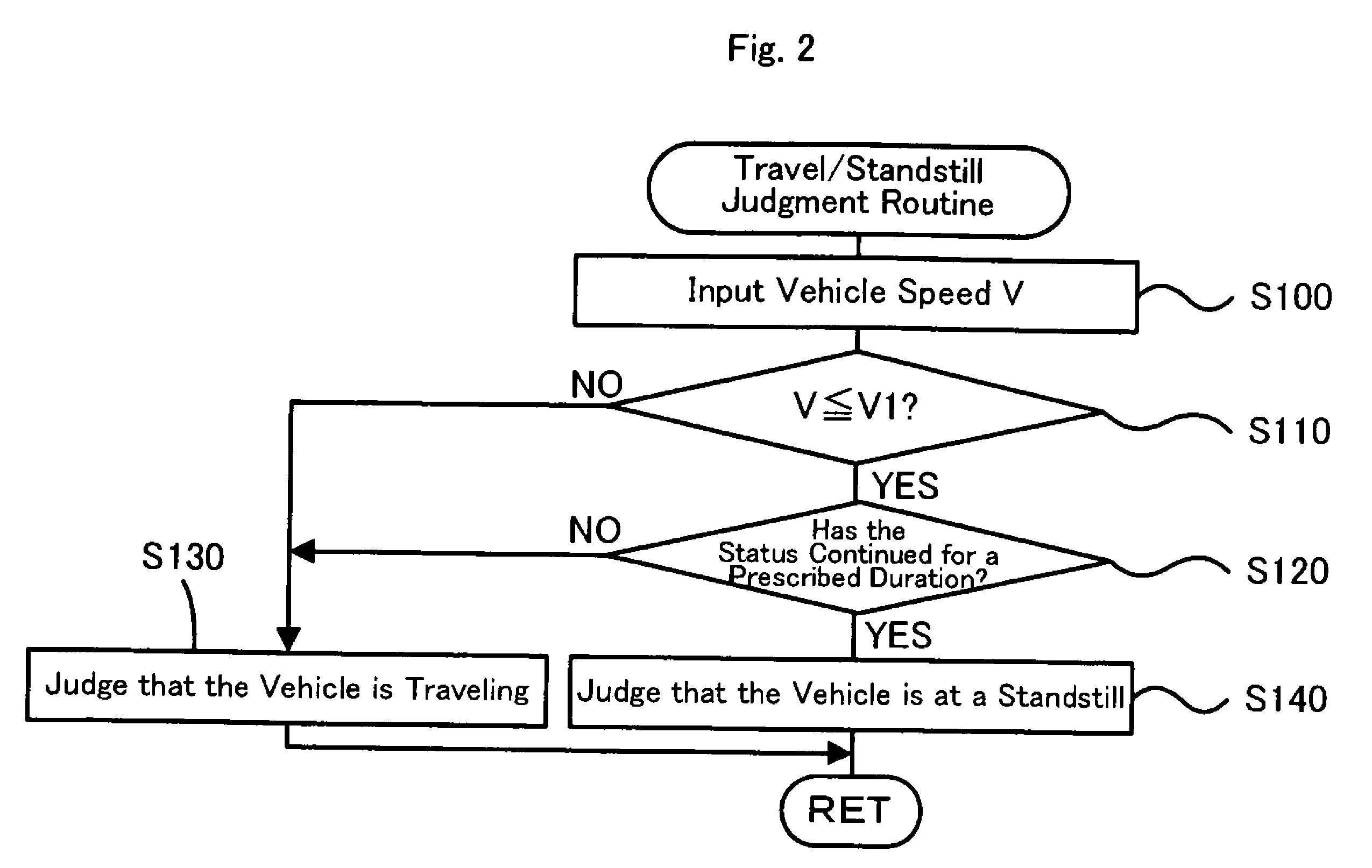
[0023]In the control method of the driving apparatus of the present invention, a judgment is made according to a vehicle speed as to whether or not the vehicle is at a standstill. In a case where it has been judged that a vehicle is not at a standstill and a demand for an idle operation of an internal combustion engine has been made during a high vehicle speed travel which is such that the vehicle speed is in a prescribed high vehicle speed range, the internal combustion engine, an electric power-mechanical power input output mechanism and an electric motor are controlled so that an idle operation of the internal combustion engine is performed at a first rotation speed and the vehicle travels by use of the drive power demand required for the travel. And in a case where it has been judged that a vehicle is not at a standstill and a demand for an idle operation of an internal combustion engine has been made during a low vehicle speed travel which is such that the vehicle speed is in a prescribed low vehicle speed range, the internal combustion engine, an electric power-mechanical power input output mechanism and an electric motor are controlled so that an idle operation of the internal combustion engine is performed at a second rotation speed higher than the first rotation speed and the vehicle travels by use of the drive power demand required for the travel. This is because as described above, the generation of vibrations and noise due to gear rattling and the like is suppressed thereby. Furthermore, in a case where it has been judged that a vehicle is at a standstill and a demand for an idle operation of an internal combustion engine has been made, the internal combustion engine is controlled so that an idle operation is performed at a third rotation speed lower than the second rotation speed. As a result of this, it is possible to improve the fuel consumption of a vehicle during an idle operation of an internal combustion engine when the vehicle is at a standstill. Incidentally, examples of a vehicle at a standstill include a case where a brake is operated by the driver, and a case where the shift position of the transmission is a parking position, and usually it is thought that the drive wheel is locked. Therefore, when an internal combustion engine is operated at idle at the third rotation speed that is relatively low, it might be thought that the possibility that the driver feels vibrations, noise and the like is weak.

Problems solved by technology

In general, in such a vehicle, improving the fuel consumption of the vehicle is considered to be one of the important problems.
In this case, however, the fuel consumption of the engine increased compared to the case of the self-supporting operation of the engine at a low rotation speed.

Method used


Image

  • Vehicle, driving apparatus and control method of both
  • Vehicle, driving apparatus and control method of both
  • Vehicle, driving apparatus and control method of both

Examples


Embodiment Construction

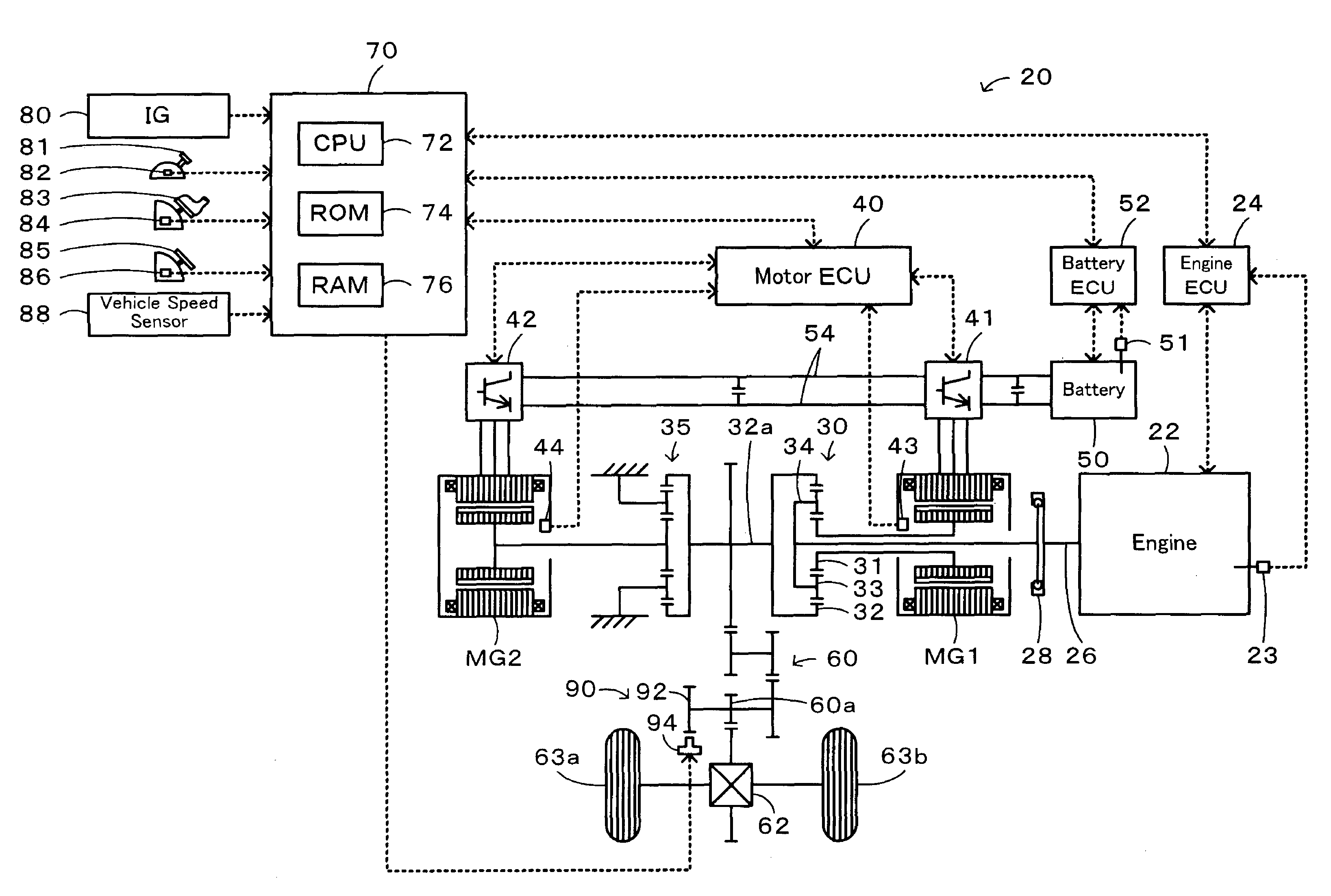
[0036]One mode of carrying out the invention is discussed below as a preferred embodiment. FIG. 1 schematically illustrates the construction of a hybrid vehicle 20 in one embodiment of the invention. As illustrated, the hybrid vehicle 20 of the embodiment includes an engine 22, a three shaft-type power distribution integration mechanism 30 that is linked with a crankshaft 26 functioning as an output shaft of the engine 22 via a damper 28, a motor MG1 that is linked with the power distribution integration mechanism 30 and is capable of generating electric power, a reduction gear 35 that is attached to a ring gear shaft 32a functioning as a drive shaft connected with the power distribution integration mechanism 30, another motor MG2 that is linked with the reduction gear 35, and a hybrid electronic control unit 70 that controls the whole motor vehicle.

[0037]An engine 22 is an internal combustion engine that outputs power by use of a hydrocarbon-based fuel, such as gasoline and light o...


PUM


Abstract

During a standstill, a prescribed rotation speed N3, which is lower than a prescribed rotation speed N2 used during a travel at a low vehicle speed, is set as a minimum rotation speed Nemin (S410), and when a demand for an idle operation has been made (S490), the minimum rotation speed Nemin is set as a target rotation speed Ne* and the value 0 is set as a target torque Te* (S500), whereby an engine is controlled. As a result of this, it is possible to improve the fuel consumption of a vehicle when the engine is operated at idle at standstill compared to a case where the engine is operated at idle at the minimum rotation speed Nemin for which the prescribed rotation speed N2 is set regardless of whether or not the vehicle is at a standstill.

Description

BACKGROUND OF THE INVENTION[0001]1. Field of the Invention[0002]The present invention relates to a vehicle, a driving apparatus and a control method of the vehicle and the driving apparatus.[0003]2. Description of the Related Art[0004]There has hitherto been proposed a vehicle that comprises an engine, a planetary gear mechanism (a power distribution and integration mechanism) whose carrier is connected to a crankshaft of the engine and whose ring gear is connected to a drive shaft coupled to a drive wheel, a first motor (motor MG1) connected to a sun gear of the power distribution and integration mechanism, and a second motor (motor MG2) connected to the drive shaft as a vehicle of this kind (refer to Japanese Patent Laid-Open No. 2006-233799). In this vehicle, in the self-supporting operation of an engine at a vehicle speed below a prescribed vehicle speed, by the self-supporting operation of the engine at a prescribed self-supporting rotation speed Nhi, which is a relatively high...

Claims


Application Information

Patent Timeline
Patent Type & Authority Patents(United States)
IPC IPC(8): B60K1/02H02P3/00H02P7/00B60W10/06B60W20/00H02P1/00B60L50/16
CPCB60K6/40B60K6/445B60K6/448B60W10/06B60W10/08B60W20/00B60K6/365B60K1/02Y10T477/30B60W2520/10B60W2710/065Y02T10/6243Y02T10/6286Y02T10/6239Y10S903/903Y10S903/93Y10S903/96Y10T477/23Y02T10/62B60W20/10B60W40/105
Inventor KIMURA, AKIHIROHASHIMOTO, TOSHIYAOYAMA, SHUNSUKEYAMAMOTO, MASAYAUEOKA, KIYOSHIROIKEMOTO, NORIAKINOMURA, MASAKI
Owner TOYOTA JIDOSHA KK
Why Eureka
Eureka Blog
Learn More