Collecting plate, fuel cell, and method for manufacturing same

a technology of fuel cells and collecting plates, which is applied in the direction of cell components, final product manufacturing, sustainable manufacturing/processing, etc., can solve the problems of reducing the rigidity of the output terminal, affecting the start-up characteristics, and being more susceptible to damage or deterioration. , to achieve the effect of good rigidity, high-voltage resistance, and weight reduction

Inactive Publication Date: 2011-05-24
TOYOTA JIDOSHA KK
View PDF23 Cites 13 Cited by
  • Summary
  • Abstract
  • Description
  • Claims
  • Application Information

AI Technical Summary

Benefits of technology

[0012]As fuel cells have become lighter in weight in recent years, however, there has been an expectation that the collecting plates (separators and terminal plates) will be made thinner. In particular, since high voltage is obtained from stacked fuel cells, terminal plates that are thick enough to collect such high voltage have a large thermal capacity, steal heat generated by adjacent end cells, and tend to adversely affect start-up characteristics at low temperature, so a thinner plate is also desirable from the standpoint of reducing thermal capacity.
[0013]However, when collecting plates are made thinner in an effort to achieve a lighter weight, the output terminals provided extending from the collecting sections (the main parts of these collecting plates) also end up being thinner, so there is a decrease in the rigidity of the output terminals, making them more susceptible to damage or deterioration.
[0014]In view of this, it is an object of the present invention to provide a collecting plate that has lower weight and lower thermal capacity while retaining good rigidity and high-voltage resistance, and to provide a fuel cell in which this is used, and a method for manufacturing these.

Problems solved by technology

In particular, since high voltage is obtained from stacked fuel cells, terminal plates that are thick enough to collect such high voltage have a large thermal capacity, steal heat generated by adjacent end cells, and tend to adversely affect start-up characteristics at low temperature, so a thinner plate is also desirable from the standpoint of reducing thermal capacity.
However, when collecting plates are made thinner in an effort to achieve a lighter weight, the output terminals provided extending from the collecting sections (the main parts of these collecting plates) also end up being thinner, so there is a decrease in the rigidity of the output terminals, making them more susceptible to damage or deterioration.

Method used


Image

  • Collecting plate, fuel cell, and method for manufacturing same
  • Collecting plate, fuel cell, and method for manufacturing same
  • Collecting plate, fuel cell, and method for manufacturing same

Examples


first embodiment

Constitution of Fuel Cell

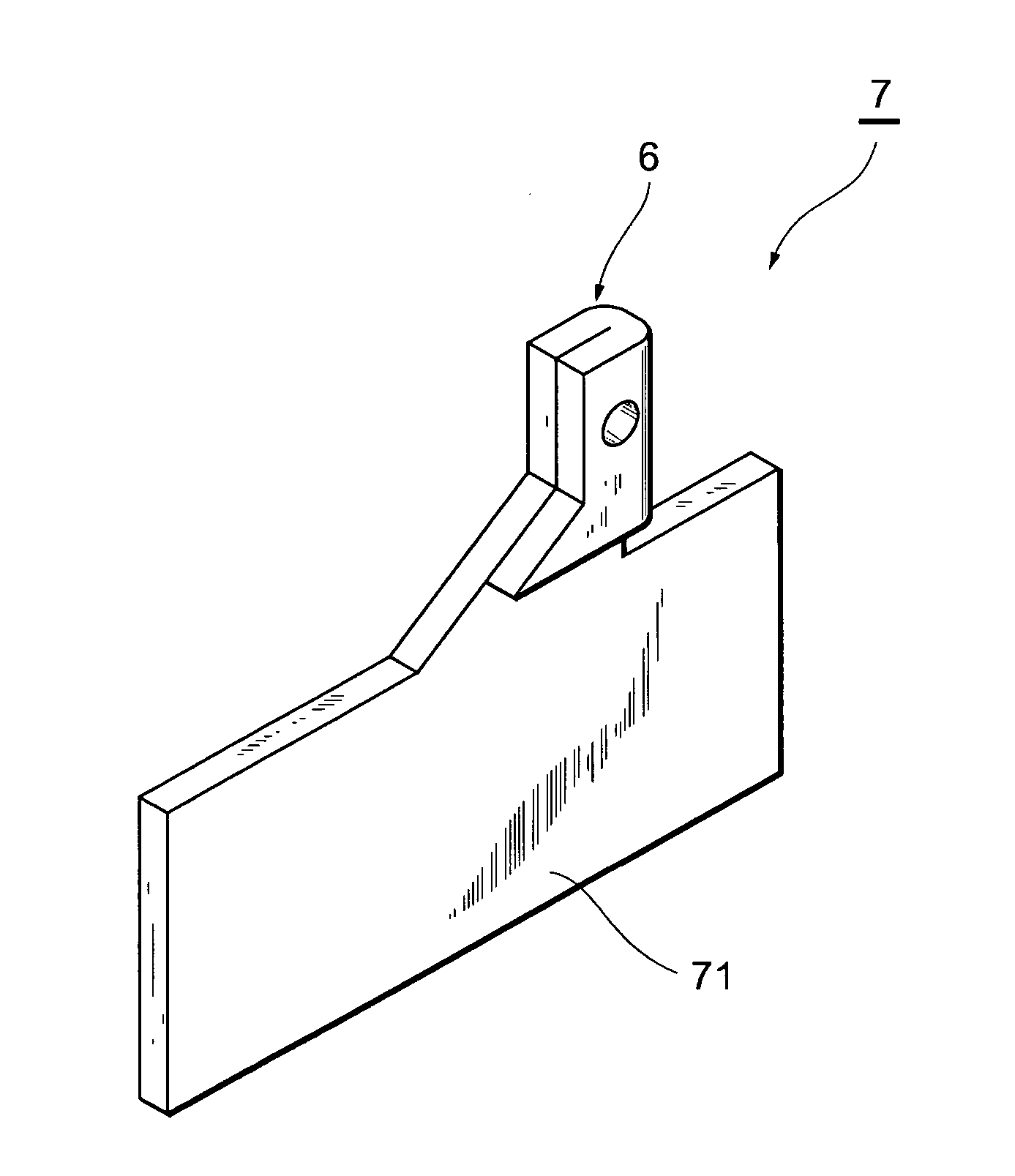
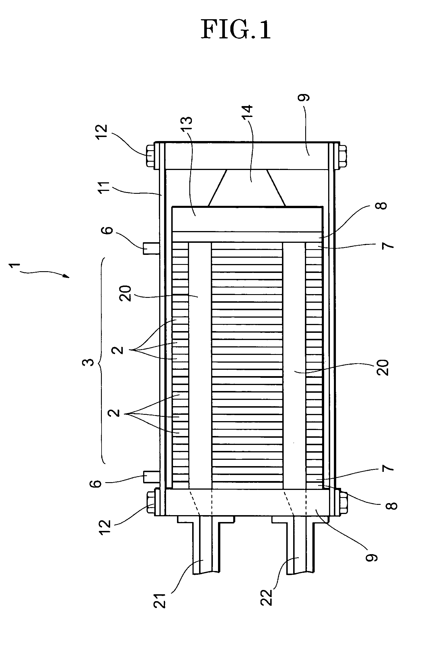
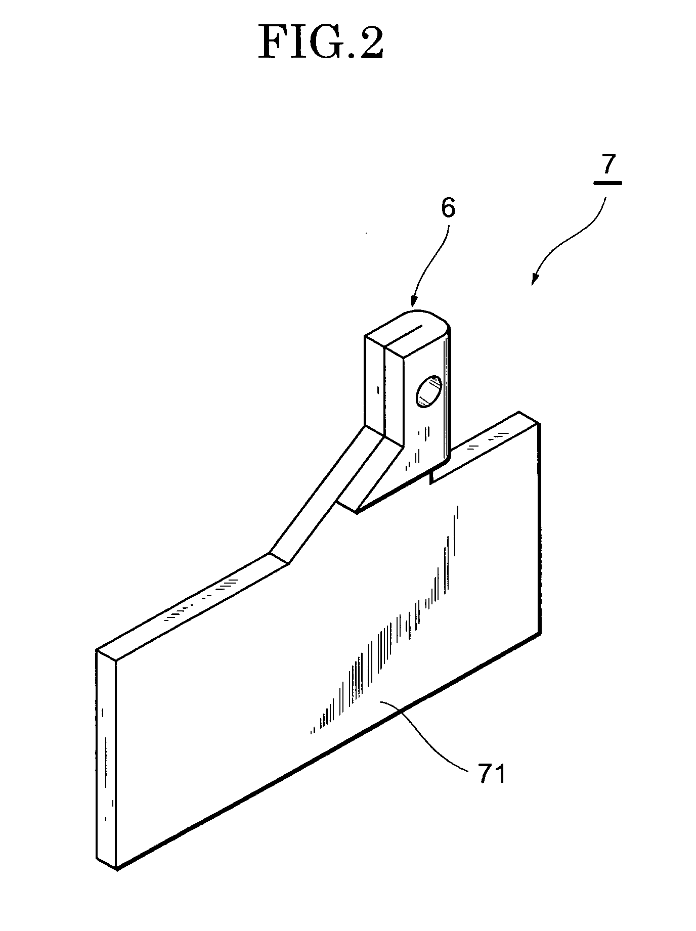
[0074]As shown in FIG. 1, a solid polymer type of fuel cell 1 has a stack 3 produced by stacking numerous single cells 2, which are the basic cells. The fuel cell 1 is the product of stacking a terminal plate 7 (collecting plate) with an attached output terminal 6, an insulating plate 8, and an end plate 9, in that order, on the outside of the single cells 2 located at each end of the stack 3.

[0075]Tension plates 11 provided spanning the two end plates 9, for example, are fixed by bolts 12 to the end plates 9, so that the fuel cell 1 is in a state in which a specific compressive force is exerted (applied) in the cell stacking direction. A pressure plate 13 and a spring mechanism 14 are provided between the insulating plate 8 and the end plate 9 at one end of the stack 3, so that fluctuations in the load exerted on the single cells 2 are absorbed.

[0076]Although not shown in the drawings, the single cells 2 are made up of a MEA (Membrane Electrode Assembly) co...

second embodiment

[0095]A second embodiment of the collecting plate pertaining to the present invention will now be described through reference to FIG. 6. The only differences in this second embodiment from the first embodiment discussed above are that an output terminal forming portion 33 is bent a plurality of times to form an output terminal 32, and that rigidity increasing means 31 is provided to the output terminal forming portion 33, with the rest of the constitution being the same as in the first embodiment.

[0096]In the first embodiment above, an example was described in which the plate thickness of the collecting section 71 was only half that the conventional thickness, and the output terminal 6 was formed by bending the output terminal forming portion 61 just one time, but in this second embodiment, a situation will be described in which the plate thickness of the collecting section 71 is even thinner than in the past (such as one-fourth) in an effort to further reduce the thermal capacity a...

third embodiment

[0101]A third embodiment of the collecting plate pertaining to the present invention will now be described through reference to FIG. 7. The only differences in this third embodiment from the first embodiment discussed above are that an output terminal 52 is formed without bending an output terminal forming portion 51, and that rigidity increasing means 53 is provided to the output terminal forming portion 51, with the rest of the constitution being the same as in the first embodiment.

[0102]Specifically, a terminal plate 50 (collecting section) in this embodiment comprises the rigidity increasing means 53, in the form of a kind of buttress, provided to the proximal end 54 of the output terminal forming portion 51 connecting to the collecting section 71. As shown in FIG. 7, the width L1 of the proximal end 54 of the collecting section 71 in the planar direction (the lengthwise direction of the collecting section 71 in FIG. 7) and the width L0 of the output terminal 52 in the planar di...


PUM

PropertyMeasurementUnit
thicknessaaaaaaaaaa
rigidityaaaaaaaaaa
widthaaaaaaaaaa

Abstract

The collecting plate of the present invention is used in a stacked fuel cell, and comprises a collecting section and an output terminal that is electrically connected to the collecting section and has a thickness that is greater than the thickness of the collecting section. For example, the output terminal is formed by bending at least part of an output terminal forming portion that is extended from the collecting section, at least one time.

Description

BACKGROUND OF THE INVENTION[0001]1. Field of the Invention[0002]This invention relates to a collecting plate, a fuel cell, and a method for manufacturing the same.[0003]2. Description of Related Art[0004]Conventional solid polymer electrolyte fuel cells have, for example, individual cells made up of a membrane-electrode assembly (MEA) consisting of an electrolyte membrane composed of an ion exchange membrane, an electrode (anode, fuel electrode) composed of a diffusion layer and a catalyst layer disposed on one side of this membrane, and an electrode composed of a diffusion layer and a catalyst layer disposed on the other side of the electrode membrane, and a separator that forms a channel for supplying fuel gas and oxidizing gas to the anode and cathode, respectively. A plurality of these single cells are stacked, a terminal plate, an insulating plate, and an end plate are disposed in that order on both ends (in the cell stacking direction) of this stack, and these are fastened tog...

Claims


Application Information

Patent Timeline
Patent Type & Authority Patents(United States)
IPC IPC(8): H01M4/64H01M4/66H01M8/24H01M2/20
CPCH01M8/0247Y10T29/49002Y10T29/49108Y02E60/50Y02P70/50
Inventor ICHIOKA, TADAHIRO
Owner TOYOTA JIDOSHA KK
Why Eureka
Try Eureka