Electromagnetic pressure regulating valve device having an integrated pressure sensor

a technology of electronic pressure regulation and valve device, which is applied in the direction of fluid pressure control, process and machine control, instruments, etc., can solve the problems of inability to adequately compensate either the time variance of the controlled system, stationary and dynamic performance is therefore unsatisfactory, and both the amplitude and phase of the signal change, so as to reduce the filter effect of the transmission link, the effect of reducing the filter effect and ensuring the accuracy of the control valv

Inactive Publication Date: 2011-05-31
ROBERT BOSCH GMBH
View PDF28 Cites 12 Cited by
  • Summary
  • Abstract
  • Description
  • Claims
  • Application Information

AI Technical Summary

Benefits of technology

[0004]The present invention relates to measuring the hydraulic pressure to be measured as close as possible to the valve part, since this is where the pressure change is produced. The pressure sensor is therefore provided on an end of the solenoid part facing the valve part. Positioning the pressure sensor close to the valve part substantially reduces the filter effect of the transmission link, and the hydraulic pressure to be measured is therefore transmittable free of errors up to a much higher cutoff frequency. This results in a higher measurement accuracy, and therefore also a higher regulation accuracy, of the pressure regulating valve.
[0008]Due to the shorter distances for the electrical transmission of the sensor signals, costly shielding may be eliminated. In integrating the control and power electronics into the pressure regulating valve, this may be implemented using only three connecting lines. The supply voltage is transmitted via one line, the reference variable (pressure) and diagnosis / status information via a further bidirectional line, while a third line forms the connection to ground. This reduces the number of connecting lines between the central control unit and the pressure regulating valve from five to three lines. In particular, it may be advantageous if low-power-conducting lines are eliminated, and along with them the problem of the resulting poor self-cleaning of contacts in contaminated environments. The only signal line thus transmits, for example, both the reference variable and the diagnosis / status signal using a bidirectional protocol. A pulse-width-modulated signal, for example, is used to improve electromagnetic sturdiness. The transmission may be carried out digitally and using timing. This protocol has the following advantages:
[0011]Its current intensity may be set in such a way that the self-cleaning of electric contacts is of sufficient quality, and power loss nevertheless does not become too high.

Problems solved by technology

This principle has two important disadvantages: It is not possible to adequately compensate either the time variance of the controlled system, due to changes in the ambient conditions (such as temperature), or disturbance variables (such as changes in supply pressure).
Both the stationary and dynamic performance are therefore unsatisfactory.
As a result, both the amplitude and phase of the signal changes, which is disadvantageous insofar as the pressure signals are transmittable true to original only up to a relatively low cutoff frequency.
Consequently, undesirable corruption of the measurement result may occur.
Positioning the pressure sensor directly on or in the valve part itself may not be possible in practice due to the fact that pressure regulating valves are often inserted via their valve part into a receptacle hole of a valve block, and only the solenoid part protrudes from the receptacle hole.
Due to space constraints, therefore, the pressure sensor connected to electric cables may not be able to be placed directly on the valve part.
However, this gives rise to the danger of the sensor signal being corrupted due to electromagnetic interference.

Method used


Image

  • Electromagnetic pressure regulating valve device having an integrated pressure sensor
  • Electromagnetic pressure regulating valve device having an integrated pressure sensor
  • Electromagnetic pressure regulating valve device having an integrated pressure sensor

Examples


Embodiment Construction

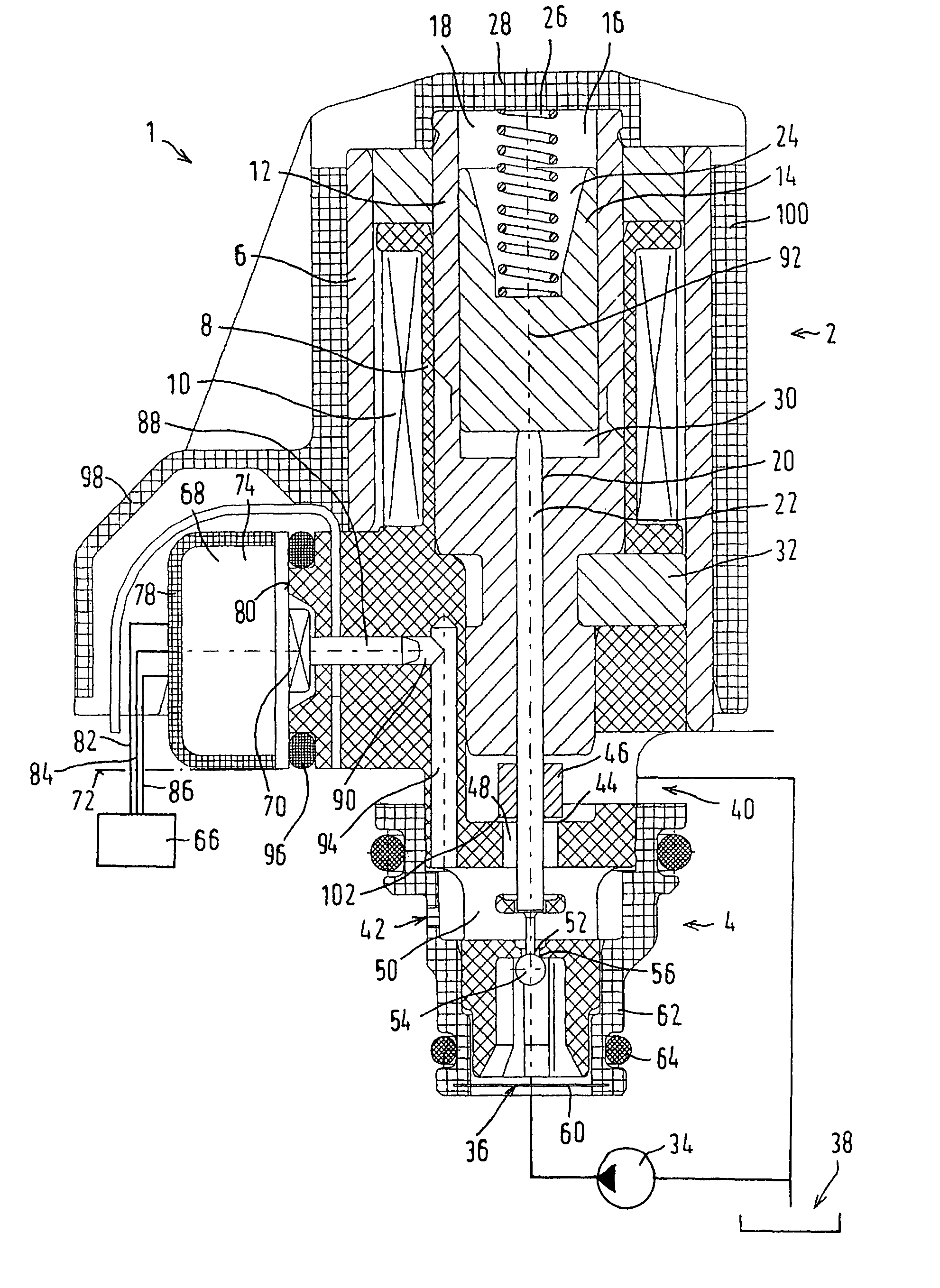
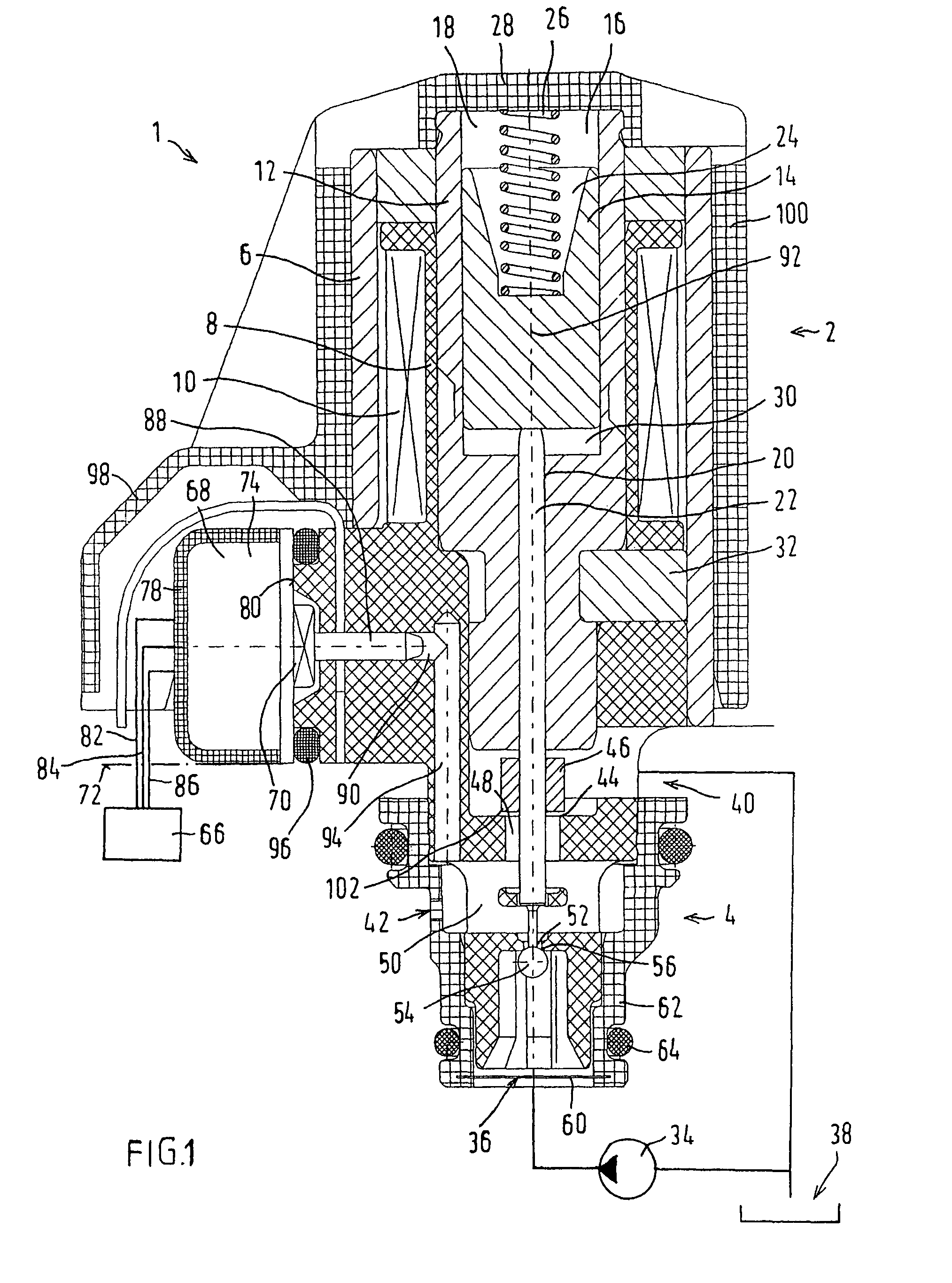
[0018]The preferred exemplary embodiment shown in FIG. 1 of an electromagnetic pressure regulating valve 1 of a pressure regulating valve device according to the present invention is used, for example, to regulate the hydraulic control pressure of a hydraulic clutch in a stepped automatic transmission of a motor vehicle. Pressure regulating valve 1 includes, among other things, a solenoid part 2 and a valve part 4.

[0019]Solenoid part 2 is enclosed by a solenoid sleeve 6 and includes a coil 10 wound on a bobbin 8, a coil core 12 projecting into the interior of coil 10 and an armature 14 which is movably guided in the axial direction in coil core 12. For this purpose, coil core 12 has a stepped core hole 16 in whose larger-diameter section 18 armature 14 is guided, while an actuating piston 22 is located in a longitudinally movable manner in a hole section 20 of smaller diameter which is adjacent to the valve part, the actuating piston contacting an end face of armature 14 on one end....


PUM


Abstract

An electromagnetic pressure regulating valve device for regulating a hydraulic pressure including at least one pressure regulating valve which includes a solenoid part having at least one bobbin holding an electric coil, a coil core and a movably guided armature; a valve part having at least one supply connection, one return connection, one load connection and one actuating element operated by the armature and cooperating with a valve seat; and an electronic part having at least one pressure sensor for measuring the hydraulic pressure present at the load connection. At least the pressure sensor is situated on an end of the solenoid part facing the valve part upstream from the electronic part. Positioning the pressure sensor close to the valve part may substantially reduce the filter effect of the transmission link, and the hydraulic pressure to be measured is therefore transmittable free of errors up to a much higher cutoff frequency. This may result in a higher measurement accuracy, and therefore also a higher regulation accuracy, of the pressure regulating valve.

Description

FIELD OF INVENTION[0001]The present invention relates to an electromagnetic pressure regulating valve device for regulating a hydraulic pressure, including a pressure regulating valve having a solenoid part which includes at least one bobbin holding an electric coil, a coil core and a movably guided armature; a valve part which includes at least one supply connection, one return connection, one load connection, and a valve closing member operated by the armature and cooperating with a valve seat; and an electronic part which includes at least one pressure sensor for measuring the hydraulic pressure present at the load connection.BACKGROUND INFORMATION[0002]To activate clutches in stepped automatic transmissions, pilot valves having downstream hydraulic amplifier elements or actuators are used to vary clutch pressures. The pilot pressure in this case is set, i.e., controlled, via a forward-directed active chain. This principle has two important disadvantages: It is not possible to ad...

Claims


Application Information

Patent Timeline
Patent Type & Authority Patents(United States)
IPC IPC(8): F16K31/36
CPCG05D16/2013G05D16/2024Y10T137/7761G05D16/20
Inventor FLEISCHER, WALTERSCHUDT, KLAUSOTT, CHRISTOFFOERCH, ULRICH
Owner ROBERT BOSCH GMBH
Why Eureka
Try Eureka