Method and arrangement for removing soils, particles or fluids from the seabed or from great sea depths

a technology of seabed soil and seabed fluid, which is applied in the direction of mechanical machines/dredgers, well accessories, sealing/packing, etc., can solve the problems of wasteful process, inability to install a conventional drilling riser and take the returns, and excessive amount of drilling mud, etc., to achieve the effect of facilitating the removal of soil

Inactive Publication Date: 2011-05-31
ENHANCED DRILLING
View PDF78 Cites 8 Cited by
  • Summary
  • Abstract
  • Description
  • Claims
  • Application Information

AI Technical Summary

Benefits of technology

The new method presented there also allows for the riser to be run before setting any casings. The reason for this possibility is that the hydrostatic pressure at the bottom of the riser can be regulated to the same or less than that of seawater from sea level, regardless of the fluid density inside the drilling riser. This is achieved by having an outlet on the riser below the surface of the water that is connected to a pump system that will be able to regulate the liquid level inside the drilling riser to a depth below sea level. In this particular way will it be possible to pump drilling fluid (mud) through the drill string and up the annulus between the riser and the drill string together with formation cuttings without fracturing or loosing returns caused by the weak topsoil formations.
There may be at least one choke line in the upper part of the drilling riser of equal or greater pressure rating than the drilling riser. By incorporating the above features a well functioning system will be achieved that can safely perform drilling operations of the top 2 hole sections. By having a surface blowout preventer on top of the drilling riser, all hydrocarbons can safely be bled off through the drilling rig's choke line manifold system.
The ability to control pressures in the bottom of the hole and at the same time and with the same equipment being able to contain and safely control the hydrocarbon pressure on surface makes the present invention and riser system completely new and unique.
In another aspect of the invention there is provided a method and system for retrieving soil, particles or fluids from the seabed or deep waters. The invention in this aspect utilizes the same principle as for controlling downhole pressure as described above, whereby a riser is lowered to the desired depth, the riser having an outlet to a pump system, which pump system is used to lower the level of the interface in the riser between the liquid in the riser and a gas above the liquid to a level somewhere between the outlet and the surface, and hence lower the pressure at the lower end of the riser as compared to sea water pressure at that depth. This methodology permits liquid to be sucked into the lower end of the riser and further into the pump. From the pump the liquid may be pumped to the surface or elsewhere.
In order facilitate removal of soils or particles from the seabed, a tubing can be lowered through the riser, or alternatively together with the riser, or be otherwise configured with an outlet or nozzle positioned to discharge at or near the lower end of the riser. Through the tubing liquid or gas can be pumped at sufficient pressure to create a jet below the lower end of the riser. The jet may be used to loosen the soils or material deposits and suspend particles from the soils or material deposit in the water, so that they may more easily be sucked into the riser together with the water.

Problems solved by technology

This is the reason for that it is not possible to install a conventional drilling riser and take the returns to the surface, before a casing is set so deep that it will isolate the weaker formation and that the soil strength is high enough to support a liquid column of water and formation cuttings (debris) up to the drilling unit above sea level.
Often this “pump and dump” procedure cause for excessive amount of drilling mud, barite weighting materials, formation solids and other chemicals to be dumped to the ocean.
Besides this practice being expensive it is also a wasteful process that can be harmful to marine life on the ocean floor.
The fracture gradient is so low that it can not support the hydrostatic pressure from a full column of seawater and formation cuttings up to the drilling platform.
Particularly for smaller diameter hole sizes these additional dynamic forces can become significant.

Method used


Image

  • Method and arrangement for removing soils, particles or fluids from the seabed or from great sea depths
  • Method and arrangement for removing soils, particles or fluids from the seabed or from great sea depths
  • Method and arrangement for removing soils, particles or fluids from the seabed or from great sea depths

Examples


Embodiment Construction

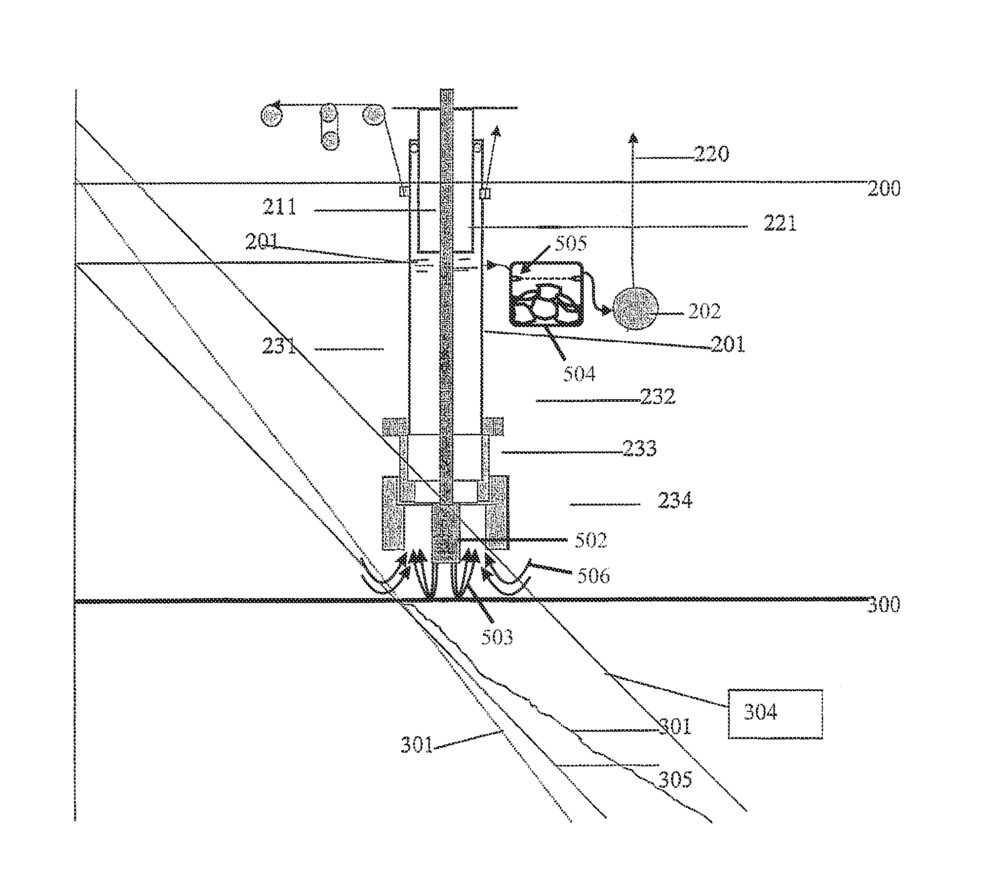
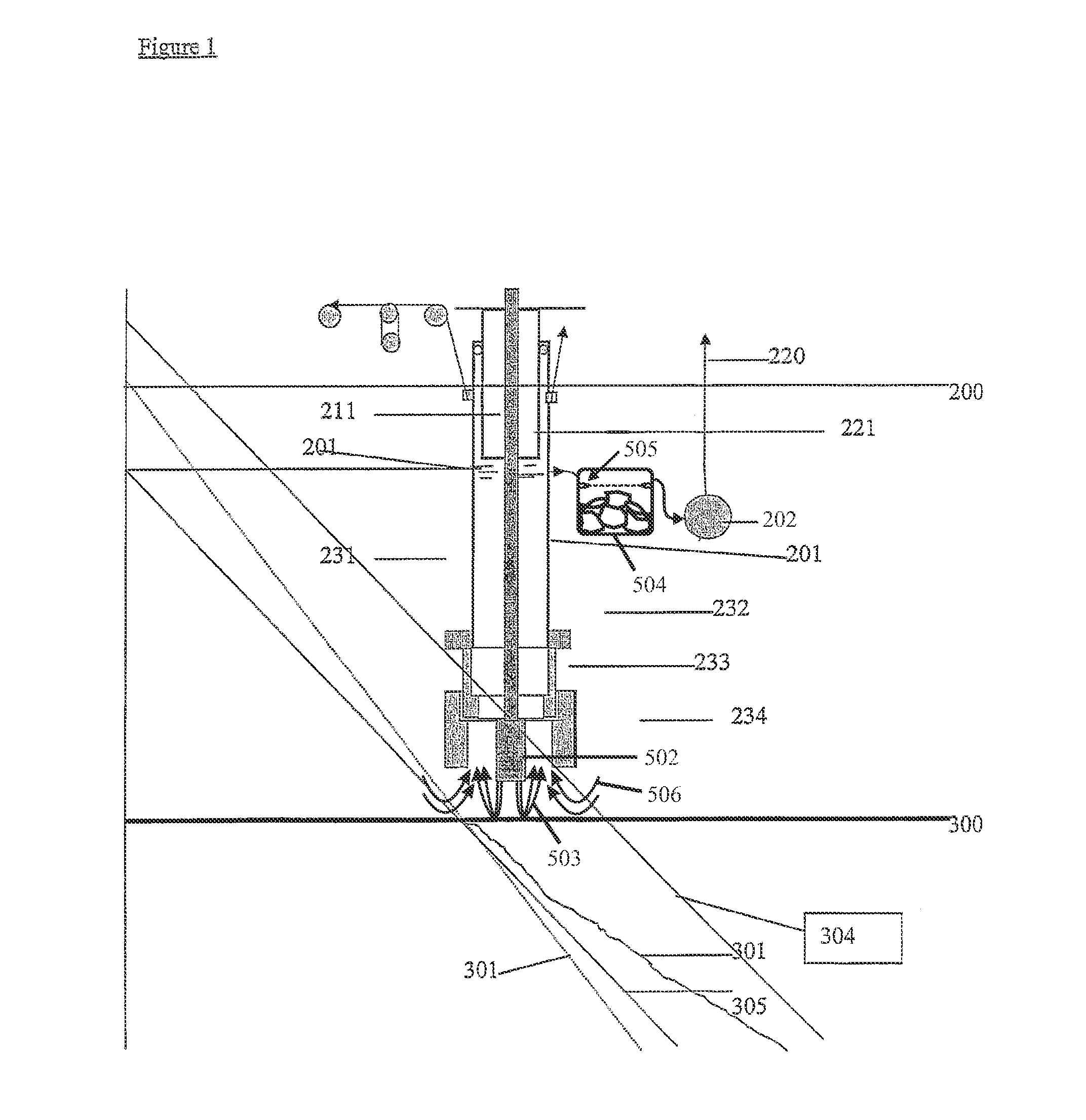
As was described in the parent application, the riser tube 201 has a lower outlet between the sea level and ocean floor with valves 204 that will divert the fluid in the riser tube into the submersible pump system which will pump the fluid and solids back up to the surface.

By being able to drop the air / liquid level in the riser to a level below sea level, it is also possible to create a pressure inside the riser which is below that of seawater, which can be seen from gradient 305 which is below that of 302 which is seawater pressure gradient from sea level 200. This implies that seawater will flow into the end of the riser tube up into the lower outlet of the riser tube into the subsea pump 202 which will pump the content through the return conduit 220 back to a surface vessel.

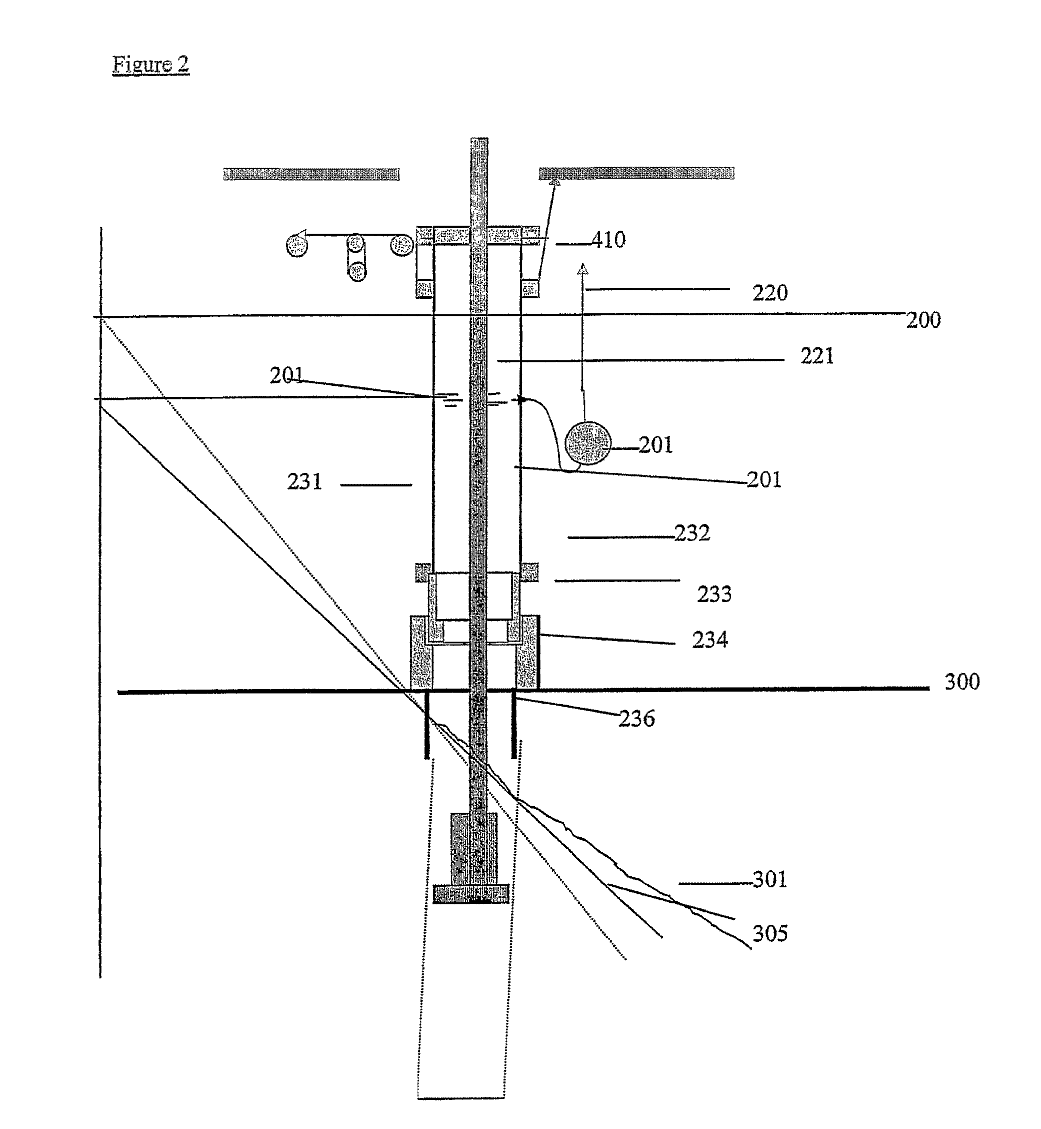
When starting the drilling operation from a floating vessel the first structural conductor 236 can be run on the end of the riser tube 201. The conductor housing 234 is connected to the surface structural cond...


PUM


Abstract

A method for removing soils, particles or fluids from the seabed or from great sea depths, includes positioning a platform or a vessel above an offshore location, lowering a riser from the vessel or platform to the seabed or great depth, the riser being vented to the atmosphere, sucking soils, particles or fluids with inflow of fluid into the riser and removing them from the riser via an outlet in the riser, the outlet being at a level well below the water surface, by use of a pumping system with a flow return conduit running to a selected location, while keeping the level of the fluid in the riser at a level between the outlet and the surface corresponding with a pressure in the lower end of the riser substantially lower than the sea water pressure at the end of the riser.

Description

FIELD OF INVENTIONThe present invention relates to a particular arrangement for use when removing soils, particles or fluids from the seabed or from great sea depths using offshore structures that float or are connected to the seabed by other means. More particularly, it describes a vented riser with an outlet to a pump system so arranged so that the liquid level in the riser can be controlled between the surface and the depth of the outlet to make the hydrostatic pressure inside the bottom of the riser equal to or below that of seawater at that depth.BACKGROUND OF THE INVENTIONExperience from subsea drilling operations in upper soil layers has shown that the subsurface formations to be drilled usually have very low fracture strength (301) close to the seabed and it is often close to that of seawater (302). This dictates that drilled formation will have to be disposed on seabed since the formation strength is not high enough to support the hydrostatic pressure from the combined effe...

Claims


Application Information

Patent Timeline
Patent Type & Authority Patents(United States)
IPC IPC(8): E21B29/12E02F3/88
CPCE21B7/12E21B7/20E21C45/00E21B21/08E21B21/001
Inventor FOSSLI, BORRE
Owner ENHANCED DRILLING
Why Eureka
Try Eureka