Electric powertrain for machine

a technology of electric powertrain and machine, applied in the direction of engine-driven generator propulsion, non-deflectible wheel steering, electric devices, etc., can solve the problems of preventing sufficient cooling, affecting the cooling effect of the engine,

Active Publication Date: 2011-05-31
CATERPILLAR INC
View PDF55 Cites 64 Cited by
  • Summary
  • Abstract
  • Description
  • Claims
  • Application Information

AI Technical Summary

Problems solved by technology

Such internal combustion engines may emit undesirable exhaust emissions and other pollutants during operation.
The use of such electric components, however, in work machines in general and in work machines having ground engaging tracks in particular, may present a number of challenges not associated with other types of vehicles.
Work machines having ground engaging tracks may be required to operate in environments typically hostile to air-cooled machinery such as, for example, swamp-like conditions or very dusty conditions.
Such conditions may render it relatively unsatisfactory to use conventional cooling systems that may rely on, for example, air filters that may quickly clog.
Furthermore, air-cooled components quickly fill with dirt or mud, thereby preventing sufficient cooling and leading to premature part failure.
As a result, conventional air-cooled electric components may not be suitable for use in work machines operating in these environments.
Work machines having ground engaging tracks may have a limited amount of space for placement of powertrain components.
Many conventional air-cooled electric motors, however, lack sufficient power density for use in a work machine.
Sometimes, however, the increase in air and fuel cannot be achieved quickly enough in response to a sudden increase in power demand for providing power to the hydraulic pump(s).
This may result in the engine lugging down or stalling.
In addition, when the internal combustion engine is able to sufficiently respond to the sudden hydraulic pump demand by increasing its engine speed, more exhaust emissions and less fuel efficiency may generally result.
The components are wired such that if the vehicle, especially a military vehicle, is partially damaged, the vehicle can continue to move.
Although the tracked vehicle of the '806 patent includes a combination of internal combustion engines, generators, and electric motors for movement, the '806 vehicle is not a work machine and does not address the problems outlined previously herein that may be associated with work machines.

Method used


Image

  • Electric powertrain for machine
  • Electric powertrain for machine
  • Electric powertrain for machine

Examples


Embodiment Construction

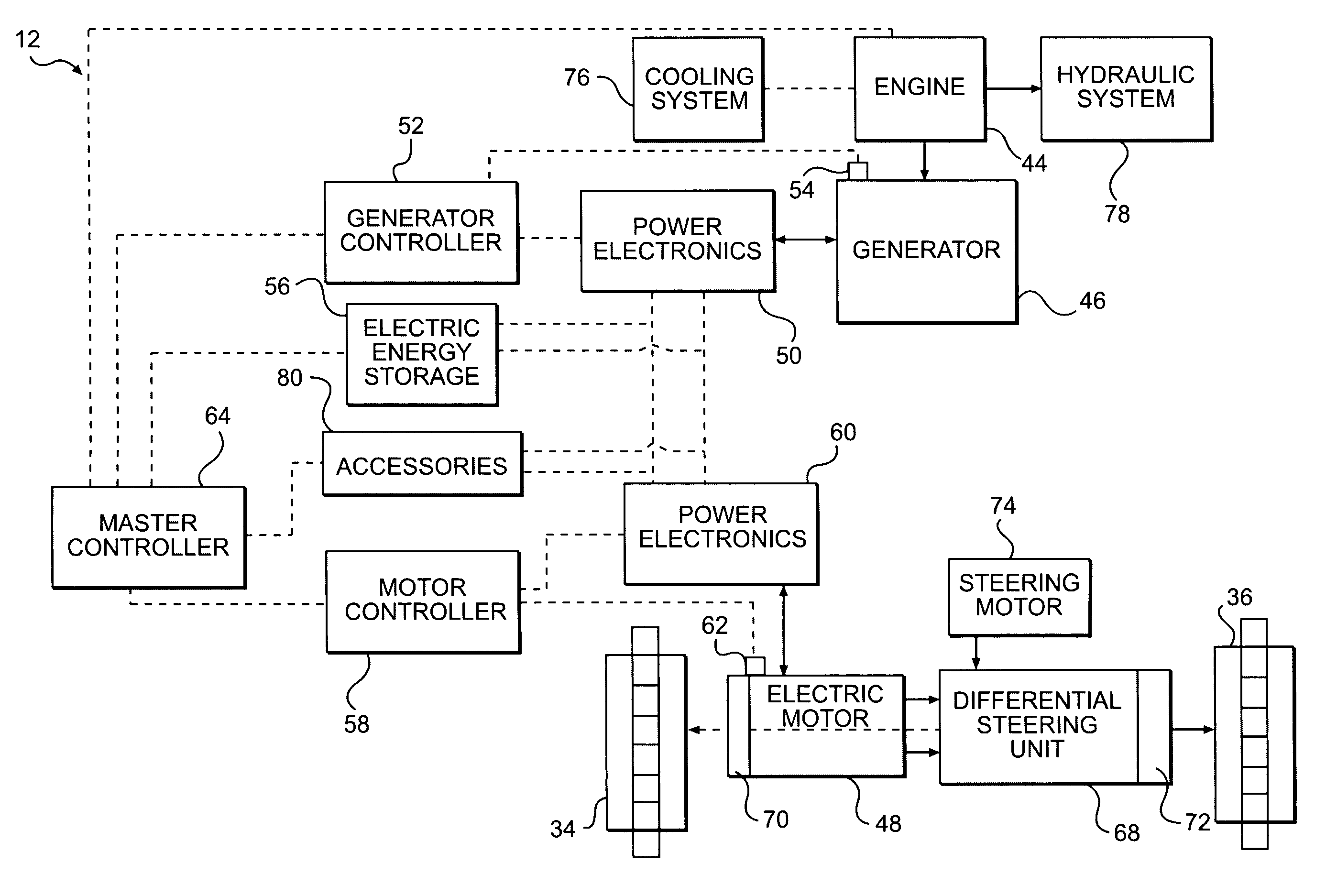
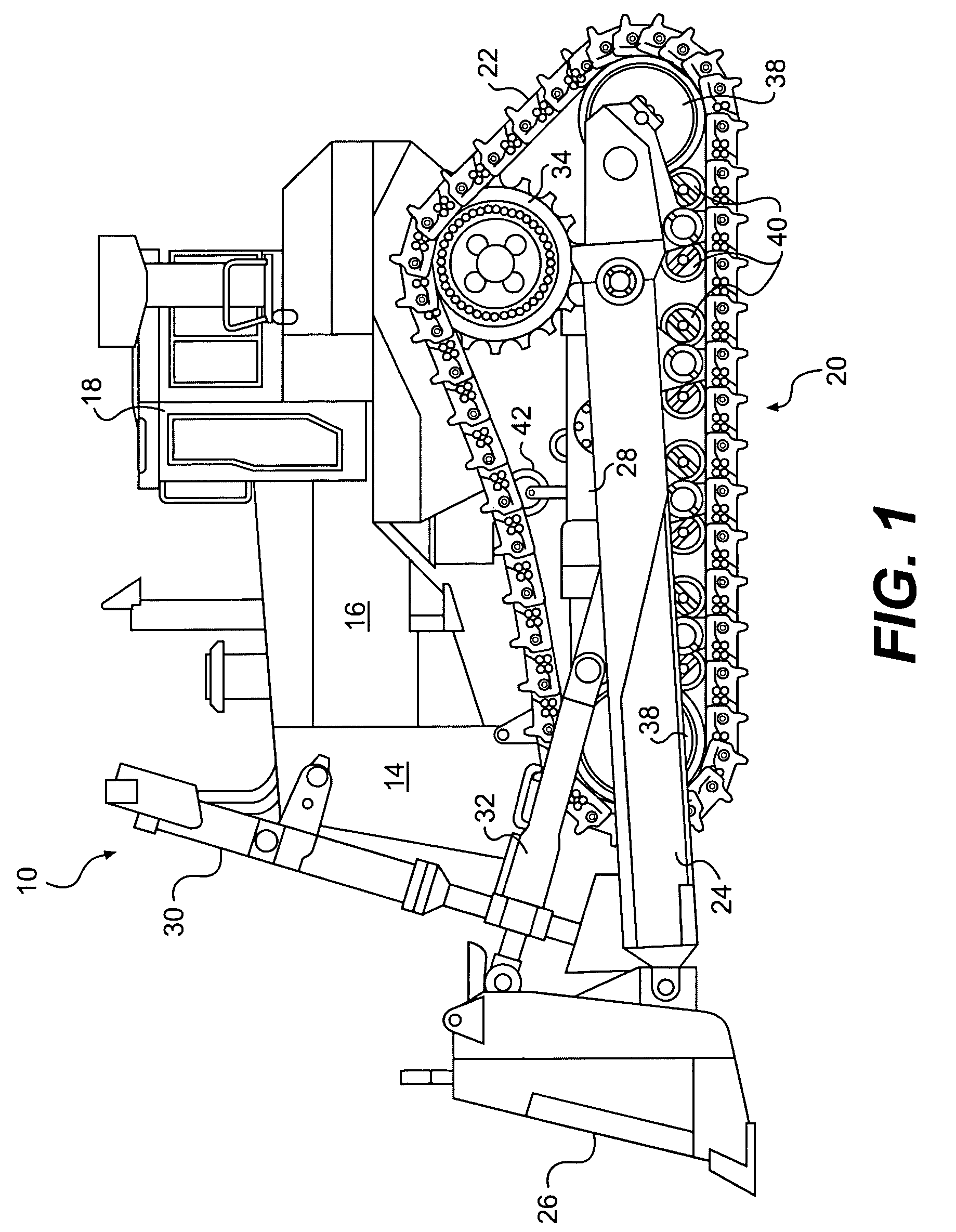
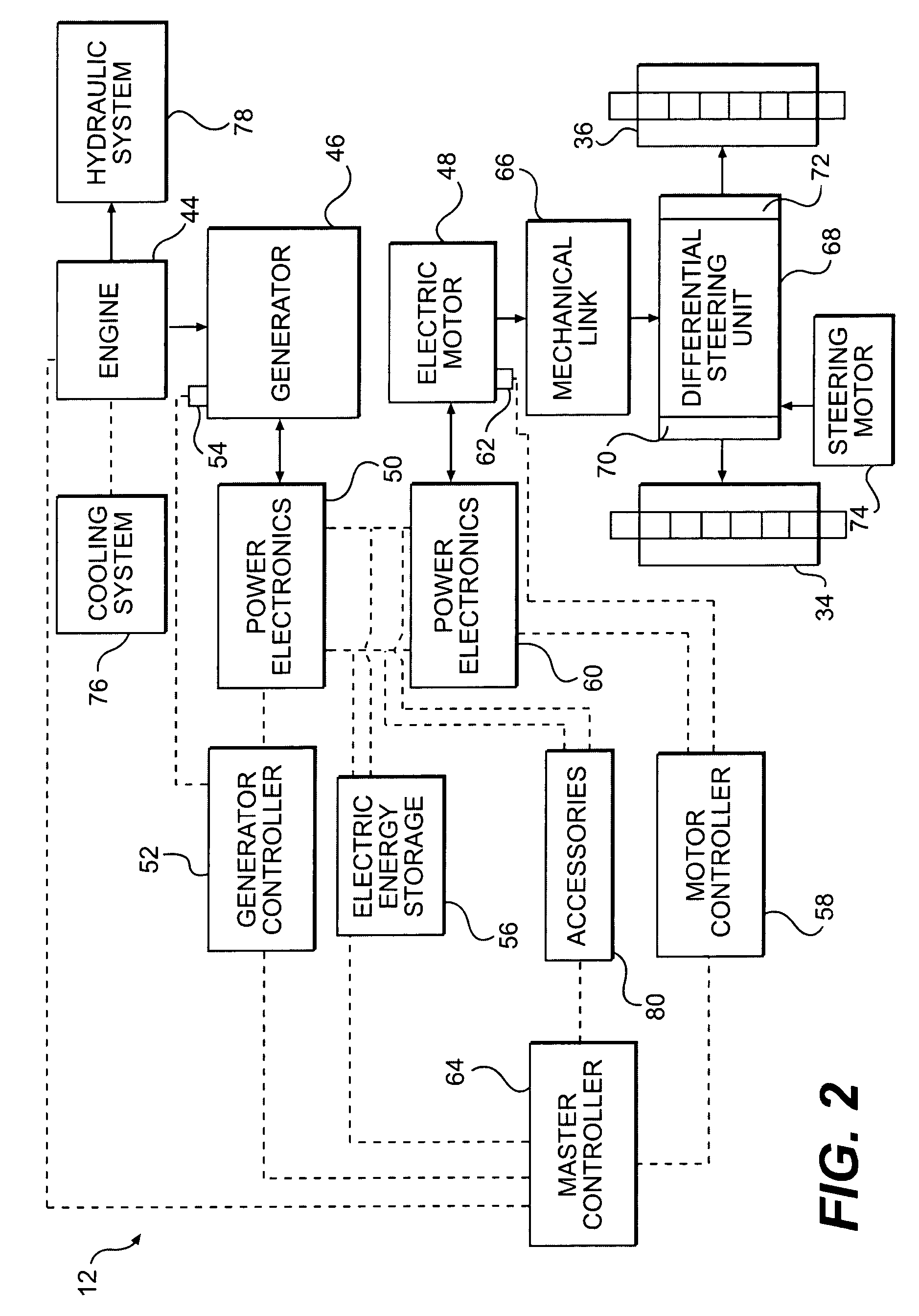
[0024]FIG. 1 illustrates an exemplary work machine 10 that may include an electric powertrain 12 (see, e.g., FIGS. 2-5). Although work machine 10 depicted in FIG. 1 is a track-type tractor, work machine 10 may be a track-type loader, a hydraulic excavator, a skid steer loader, an agricultural tractor, a wheel loader, or another work machine known to those having skill in the art. Work machine 10 may include a main frame 14 for housing a power source 16. Power source 16 may be configured to provide power to the various systems of work machine 10. Work machine 10 may also include a work station 18, and may further include an undercarriage 20 carrying ground engaging members 22 (e.g., two ground engaging tracks) located on opposite sides of main frame 14, which are configured to engage the ground and to propel work machine 10.

[0025]Undercarriage 20 may be configured to support two push arms 24 located on opposite sides of main frame 14. Push arms 24 may be connected at one end to a wor...


PUM


Abstract

An electric powertrain includes an engine configured to provide mechanical energy and a generator operably coupled to the engine and configured to convert at least a portion of the mechanical energy into electric energy. The electric powertrain further includes at least one electric motor operably coupled to the generator, a plurality of driving members, and at least one power electronics unit configured to control at least one of the engine and the generator. The at least one electric motor is configured to provide torque for the plurality of driving members.

Description

TECHNICAL FIELD[0001]The present disclosure relates generally to an electric powertrain and, more particularly, an electric powertrain for a work machine.BACKGROUND[0002]Conventional work machines such as, for example, front-end loaders, bulldozers, and excavators, may generally be powered using an internal combustion engine such as, for example, a diesel engine, a gasoline engine, or other internal combustion engine known in the art. Such internal combustion engines may emit undesirable exhaust emissions and other pollutants during operation. In recent years, and for the foreseeable future, the reduction of exhaust emissions for internal combustion engines in general and for work machines in particular, has become a regulatory priority. Furthermore, increasing fuel efficiency of vehicles and work machines has also become of increased importance, for example, to reduce increased costs associated with the rising price of fossil fuels and / or reliance on imported oil.[0003]Driven at le...

Claims


Application Information

Patent Timeline
Patent Type & Authority Patents(United States)
IPC IPC(8): B62D11/00B60K6/46B60L50/15B60L50/16
CPCB60K6/46B60L11/123B60L2220/18Y02T10/7258B60Y2200/411Y02T10/6217Y02T10/7077B60Y2200/25B60L50/61Y02T10/62Y02T10/72Y02T10/70Y02T10/7072
Inventor BETZ, MICHAEL D.CASEY, KENT A.GARNETT, STEPHEN C.LIANG, CHIH C.TONSOR, ANDREW J.VANDERHAM, MICHAEL E.ZWILLING, EDWARD L.
Owner CATERPILLAR INC
Why Eureka
Try Eureka