Apparatus for reducing drag on vehicles with planar rear surfaces

a rear surface and apparatus technology, applied in the direction of roofs, vehicle arrangements, transportation and packaging, etc., can solve the problems of reducing fuel economy, requiring a sizable replacement cost, and devices with certain drawbacks, and achieve the effect of convenient opening

Inactive Publication Date: 2011-05-31
SKOPIC JOSEPH
View PDF56 Cites 54 Cited by
  • Summary
  • Abstract
  • Description
  • Claims
  • Application Information

AI Technical Summary

Benefits of technology

[0016]According to the present disclosure, reduction of drag arising from creation of a low pressure volume of turbulent air behind a generally planar rear surface of a vehicle is provided by attaching a pair of vanes to the right and left corner edges of the rear surface of the vehicle. More particularly, the invention is directed to an apparatus for reducing drag on a moving vehicle having a substantially planar rear surface, comprising a rigid vane of length L having a leading edge, a trailing edge, and a longitudinal aerodynamic center therebetween, positioned at a distance of, for example, between 0.15 L and 0.5 L from said leading edge, preferably 0.26 L from the leading edge. The vane has an inner surface facing said vehicle and an outer surface; at least one first pliant attachment means connecting the leading edge of the vane to a side surface of said vehicle; at least one second pliant attachment means connecting the trailing edge of the vane to a rear surface of said vehicle; and at least one third pliant attachment means connecting the inner surface of the vane to the vehicle. The inner surface may be connected to the side of the vehicle or to the rear of the vehicle. The third pliant attachment means is connected to the inner surface of the vane. Preferably, the third pliant attachment means is connected to the inner surface of the vane at a distance of, for example, between 0.15 L and 0.5 L from the leading edge of the vane. More preferably, the third pliant attachment means is connected to the inner surface of the vane at the aerodynamic center of the vane. As will be understood by a person of ordinary skill in the art, based on this description, the vane helps reduce or prevent formation of a zone of turbulent air behind the rear surface of the vehicle. The outer surface of the vane is preferably curved.

Problems solved by technology

A vehicle is then required to expend energy to push this volume of air aside, thereby reducing fuel economy.
A second, and at least equally pernicious, form of resistance to a vehicle in motion lies in the drag on the vehicle caused by the formation of reduced-pressure zones at the rear of the vehicle, or in between units of a combination vehicle, such as a string of multiple trailers.
However, due to turbulence caused by the passage of the vehicle, a space filled with low pressure air forms between the rear of the vehicle and the point at which these airstreams fully recombine.
However, a number of legacy trailers exist, which would require a sizable expense to replace.
However, these devices do have certain drawbacks.
Thus, these devices may not be simply mounted on a trailer and left in place.
Similarly, such devices must be disassembled and removed from the trailer before unloading can begin, causing inconvenient delays in the unloading and loading processes.
Another drawback of using rear-mounted devices on trailers is that the devices add significantly to the length of a trailer, making it difficult to use these conical or pyramidal devices to reduce drag in between a pair of trailers mounted in series.
Some designs allow the vanes to slide into or out of tracks mounted on the side of the vehicle; while the use of such tracks accelerates the process of positioning vanes after loading and unloading the trailer, the cost and complexity of retrofitting an existing trailer with a streamlined vane is significantly increased.
However, in the case of a vehicle having hinged doors, these boattail plates impede the doors from swinging open.
In the case of a vehicle having a roll-up door, these boattail plates impede the vehicle from backing up to a loading dock.
As a result, boattail plates have not achieved wide acceptance.
While these do an effective job of preventing drag, they do impede opening the doors on the rear of the trailer.
The inability to fully open the vehicle doors is an inconvenience during the loading / unloading process.

Method used


Image

  • Apparatus for reducing drag on vehicles with planar rear surfaces
  • Apparatus for reducing drag on vehicles with planar rear surfaces
  • Apparatus for reducing drag on vehicles with planar rear surfaces

Examples


Embodiment Construction

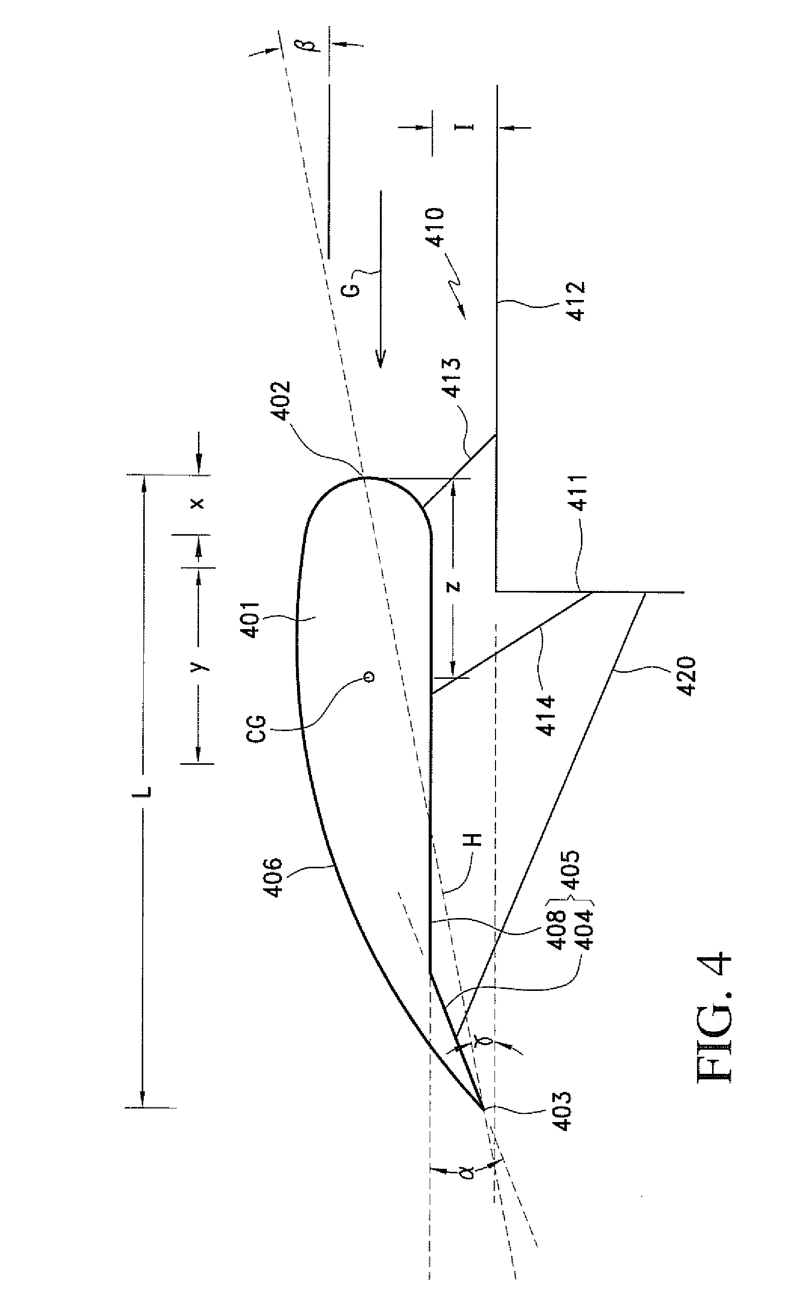
[0036]The term “aerodynamic center,” as used in this disclosure, may be defined as, but is not limited to, the point at which the pitching moment coefficient for the vane does not vary with lift coefficient. For symmetric vanes moving through an airflow, the aerodynamic center of the vane is located approximately 25% of the length of the chordline of the vane from the leading edge of the vane (the quarter-chord point). The chordline extends from the leading edge of the airfoil to the trailing edge of the vane. For non-symmetric (cambered) vanes, the quarter-chord is only an approximation for the aerodynamic center.

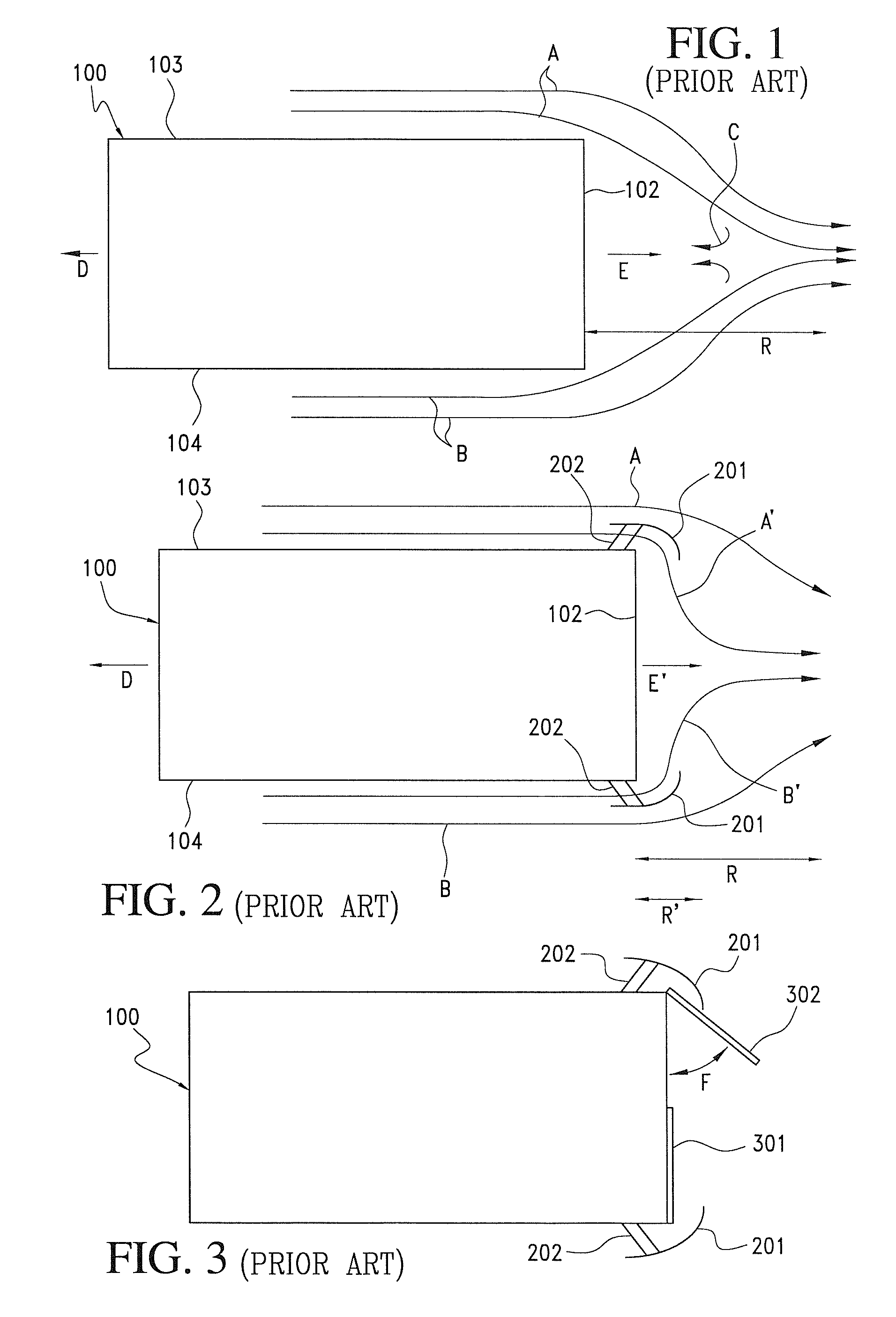
[0037]FIG. 1 shows a prior art airflow around a vehicle 100, such as a trailer, having a generally planar rear surface 102, a right side 103, and a left side 104, when vehicle 100 moves in a forward direction D at a desired speed. Under these conditions, air moves, relative to vehicle 100, along the sides 103 and 104 in the direction of arrows A and B, respectively. The fl...


PUM


Abstract

Vanes are used for reducing drag on a moving vehicle having a substantially planar rear surface. The vanes are mounted to the vehicle using pliant material which creates no work for the driver of the vehicle during loading or unloading activities. The apparatus is extremely light weight, and includes a rigid vane of length L having a leading edge, a trailing edge, and an aerodynamic center positioned at a distance of between 0.15 L and 0.5 L from the leading edge. The vane has an inner surface facing the vehicle and an outer surface. Multiple pliant attachment devices connect the vane to the vehicle. The vane helps prevent or reduce formation of a zone of turbulent air behind the vehicle. The apparatus allows substantial reductions in fuel consumption and truck CO2 emissions during use.

Description

BACKGROUND OF THE INVENTION[0001]1. Field of the Invention[0002]The invention relates generally to devices for reducing air flow resistance and drag on trucks, semitrailers, railway cars, and other vehicles. More particularly, the invention relates to devices for redirecting air from airstreams passing around a vehicle into zones of turbulent air at the rear of the vehicle.[0003]2. Description of the Prior Art[0004]The profitability of long-distance highway cargo transport depends heavily on the cost of fuel, and on the efficiency with which the fuel is utilized. The cost of fuel is largely outside the control of the cargo transporter; however, the efficiency of fuel utilization may be increased. One method involves reducing resistance to forward motion of a vehicle through the air. Resistance to vehicular motion takes two major forms. First, the volume of air immediately in front of the vehicle acts as a barrier. A vehicle is then required to expend energy to push this volume of ai...

Claims


Application Information

Patent Timeline
Patent Type & Authority Patents(United States)
IPC IPC(8): B62D35/00B61D17/00
CPCB62D35/001Y10S180/903
Inventor SKOPIC, JOSEPH
Owner SKOPIC JOSEPH
Why Eureka
Try Eureka