
Rear projector

a projector and rear-facing technology, applied in projectors, instruments, optics, etc., can solve the problems of large pupil aberration, difficult suppression of luminance non-uniformity with a usual refractive fresnel lens, and large pupil aberration, so as to achieve less luminance non-uniformity and high performance

Inactive Publication Date: 2011-05-31
KONICA MINOLTA OPTO
View PDF8 Cites 2 Cited by
  • Summary
  • Abstract
  • Description
  • Claims
  • Application Information

AI Technical Summary

Benefits of technology

"The present invention is a slim rear projector with high performance and less luminance nonuniformity on the image plane attributable to pupil aberration of a projection optical system. The invention includes a screen with a rotationally symmetric Fresnel lens and a nonaxisymmetric projection optical system with at least one reflection surface formed of a rotationally asymmetric free curved surface. The Fresnel lens cancels out pupil aberration of the projection optical system so that principal rays of beams exiting from the Fresnel lens become substantially parallel to each other."

Problems solved by technology

However, the use of a free curved surface in the nonaxisymmetric projection optical system results in occurrence of large pupil aberration.
This causes luminance nonuniformity on the image plane, and it is difficult to suppress the luminance nonuniformity with a usual refractive Fresnel lens.

Method used


Image

  • Rear projector
  • Rear projector
  • Rear projector

Examples


examples

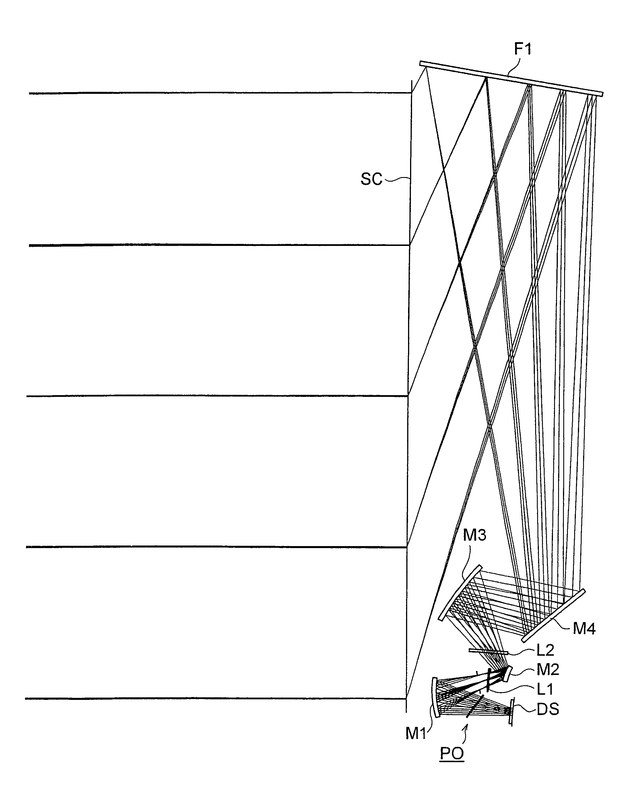
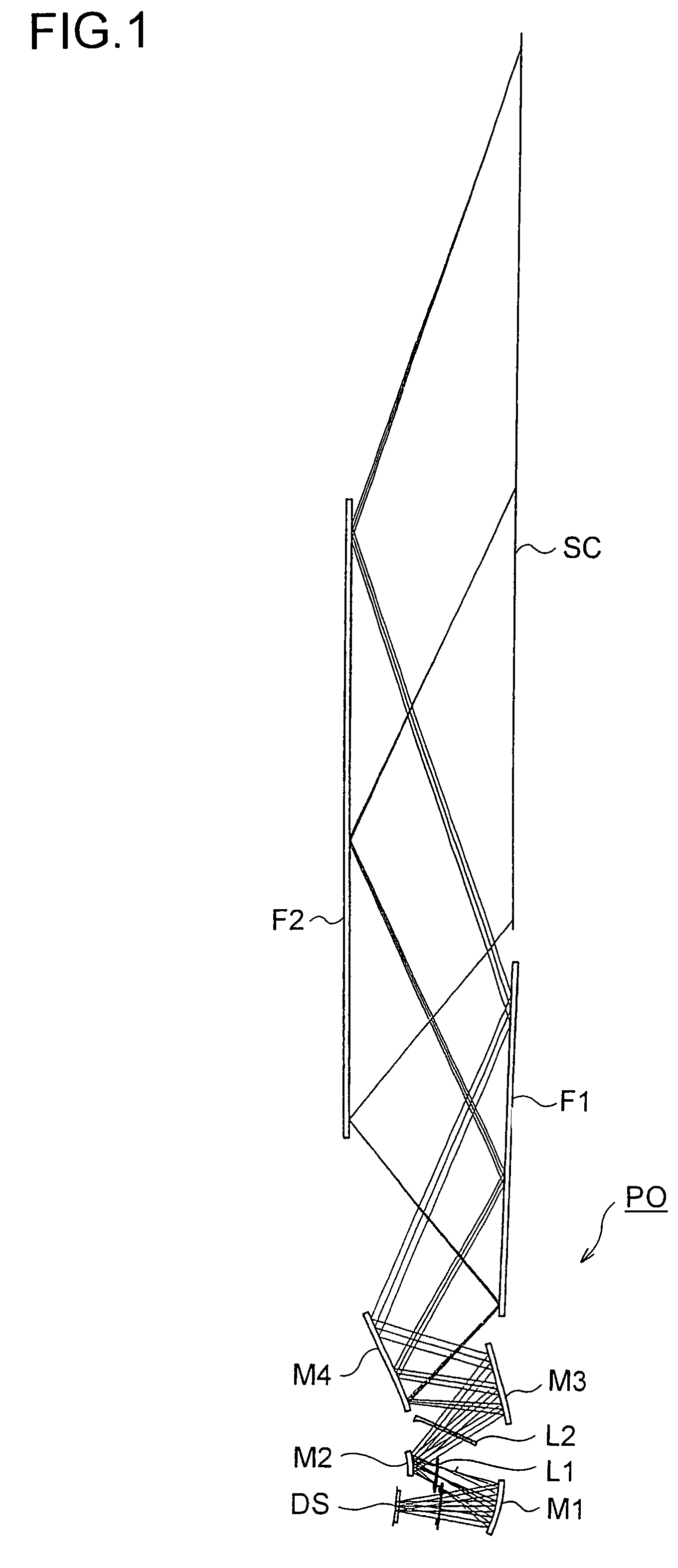
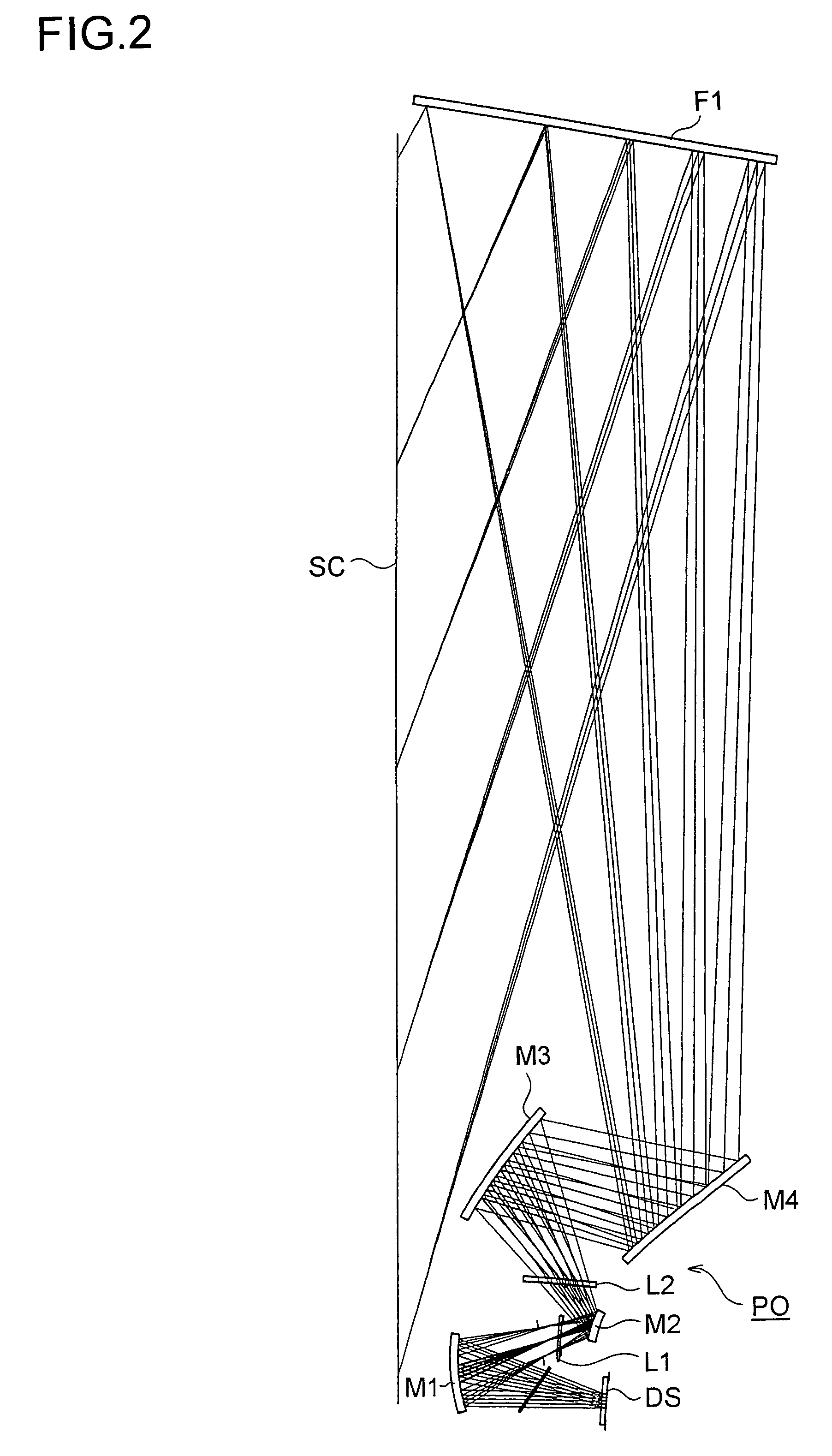
[0054]Hereinafter, optical configuration of the rear projector of the present invention will be further described in detail, with construction data and other data. Example 1, Examples 2 to 7, Example 8, and Example 9 presented below are numerical examples corresponding to the rear projectors of Types 1 to 4, respectively, described hereinbefore, and therefore the optical configuration diagrams (FIGS. 1 to 6) of the rear projectors of Types 1 to 4 show the corresponding optical configuration, projection optical paths, etc. of Examples 1, 4, 8, and 9. The construction data of the Examples indicate optical arrangement of a system including a display device surface So on the reduction side (corresponding to an object surface in enlarged projection) to a screen Si on the enlargement side (corresponding to an image surface in the enlarged projection), and the n-th surface counted from the reduction side is Sn (n=1, 2, 3, . . . ). Surfaces S1 and S2 are both surfaces of cover glass for cov...


PUM


Abstract

A rear projector for performing image projection includes: a screen and a projection optical system. The screen has a rotationally symmetric Fresnel lens. The projection optical system has at least one reflection surface formed of a rotationally asymmetric free curved surface. The projection optical system is nonaxisymmetric and makes a central principle ray incident obliquely on the screen in the image projection. The Fresnel lens has aberration that cancels out pupil aberration of the projection optical system so that principal rays of beams exiting from the Fresnel lens become substantially parallel to each other.

Description

[0001]This application is based on Japanese Patent Application No. 2006-352854 filed on Dec. 27, 2006, the contents of which are hereby incorporated by reference.BACKGROUND OF THE INVENTION[0002]1. Field of the Invention[0003]The present invention relates to a rear projector, and more specifically to a rear projector that uses, for example, a digital micromirror device or an LCD (Liquid Crystal Display) as a display device and that projects, on an enlarged scale, an image on the display device surface obliquely onto a screen surface with a projection optical system.[0004]2. Description of Related Art[0005]There have been growing demands for slimming-down of a rear projector. This slimming-down can be achieved by using a compact, wider-angle projection optical system and further providing configuration such that light exiting from the projection optical system is made incident obliquely on a screen at a relatively wide angle of incidence. As a projection optical system having a wide ...

Claims


Application Information

Patent Timeline
Patent Type & Authority Patents(United States)
IPC IPC(8): G03B21/00
CPCG03B21/62G03B21/28
Inventor IMAOKA, MASAYUKIISHIHARA, JUN
Owner KONICA MINOLTA OPTO
Learn More