Jittery signal generation with discrete-time filtering

a technology of discrete-time filtering and jittery signals, applied in the direction of line-faults/interference reduction, amplitude demodulation, pulse technique, etc., can solve the problems of increasing the number of taps, adding complexity to the design, and real transmitters and real transmission channels that do not exhibit ideal characteristics

Active Publication Date: 2011-05-31
MICRON TECH INC
View PDF13 Cites 11 Cited by
  • Summary
  • Abstract
  • Description
  • Claims
  • Application Information

AI Technical Summary

Problems solved by technology

However, real transmitters and real transmission channels do not exhibit ideal characteristics, and as mentioned above, the effects of transmission channels are becoming increasingly important in high-speed circuit design.
While such “fractionally-spaced” filtering adds complexity to the design, and generally increases the number of taps, it also provides better control of the filtering operation.
While DTFs can be a useful means to precondition data signals to combat channel-induced ISI, a DTF can be difficult to design.
Unfortunately, modeling and simulation of the DTF is difficult.
Such component-level consideration takes time and effort, which is particularly undesirable in an application in which one might be frequently changing the number of taps as well as the associated tap weights to try and find the most ideal transfer function 1 / H(z) for the DTF to compensate for a given channel.
Furthermore, modeling and simulation may not provide a suitably accurate picture of how the DTF will process signals deviating from the ideal.
Realistic data signals will not be ideal, but instead will suffer from various sources of amplitude noise and timing jitter, which noise and jitter may vary randomly between the unit intervals of the data.
Regardless of the source or type of noise or jitter, it is difficult to quickly and efficiently simulate the effects of noise or jitter in the context of a DTF circuit.
This inability to handle noise and jitter during simulation of the DTF circuit is especially problematic, because DTF circuits are particularly susceptible to noise and jitter, a point which is easy to understand when one considers that noise or jitter is in a sense multiplied by the various taps in the DTF.

Method used


Image

  • Jittery signal generation with discrete-time filtering
  • Jittery signal generation with discrete-time filtering
  • Jittery signal generation with discrete-time filtering

Examples


Embodiment Construction

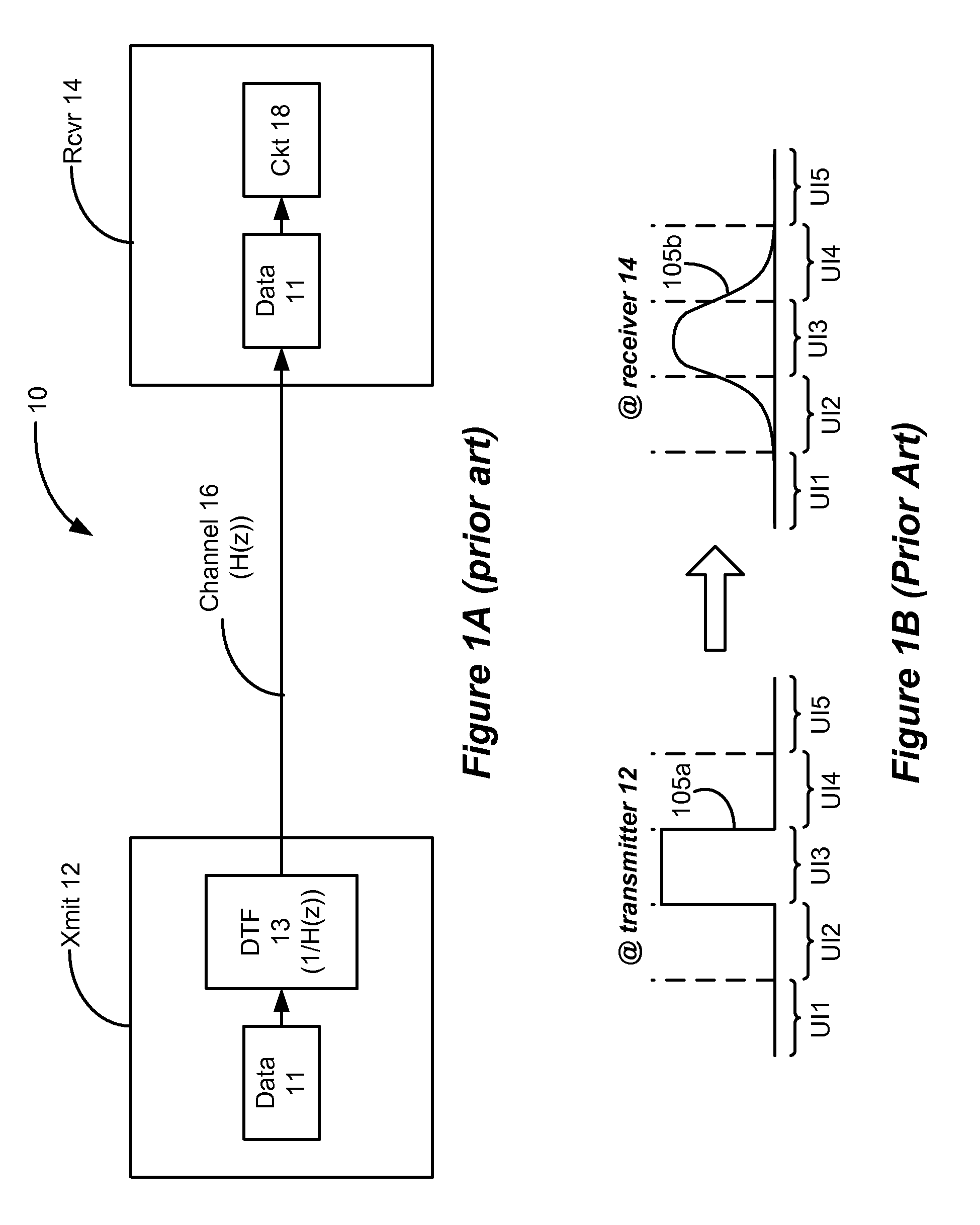
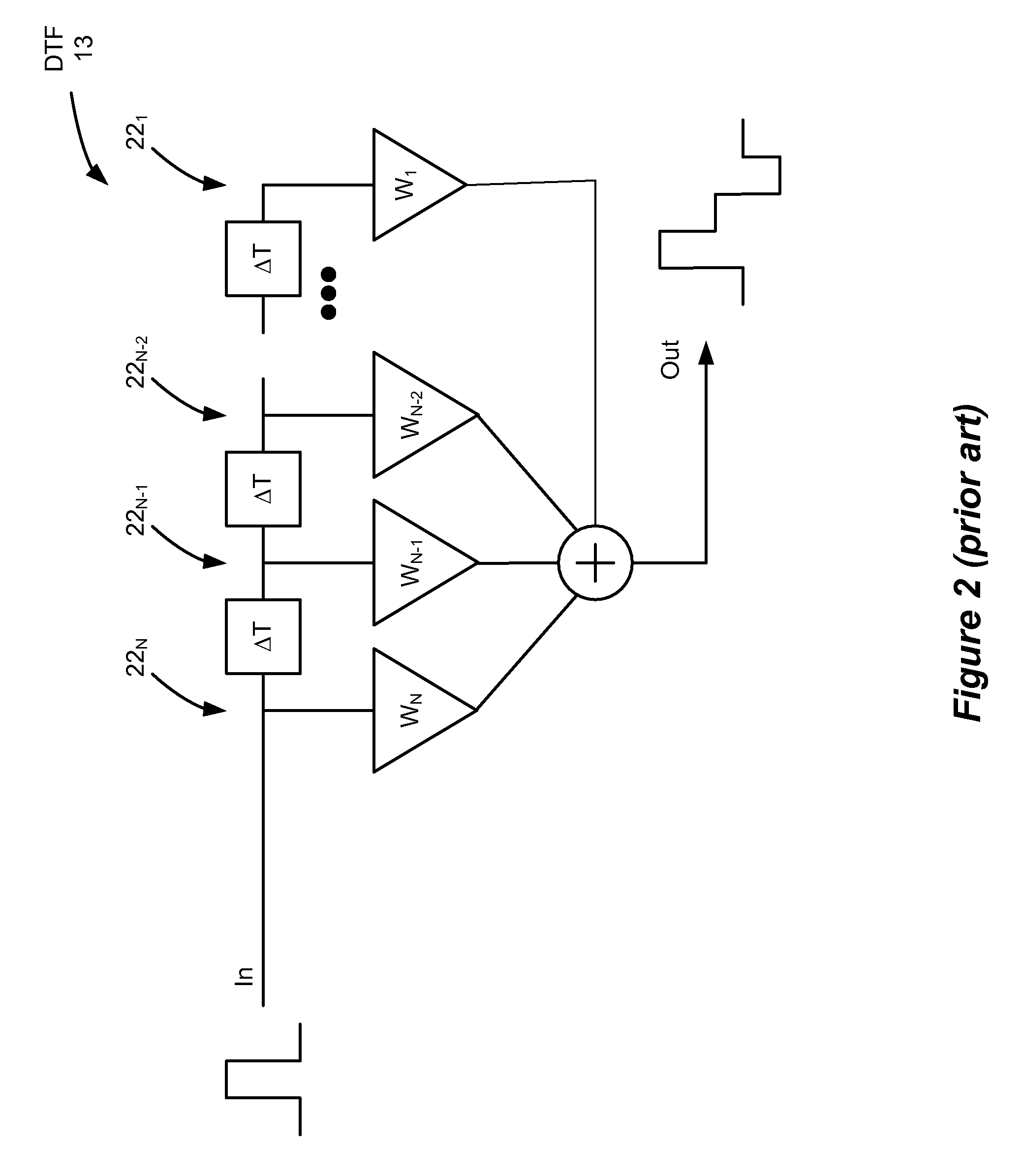
The disclosed computer-implementable method allows for the fast creation of a multi-unit-interval vector suitable for simulation. The created vector represents the output of an otherwise ideal Discrete Time Filter (DTF) circuit, and the quick creation of the vector merely requires a designer to input into a computer system the number of taps and their weights without the need of laying out or considering the circuitry of the DTF. Specifically, a matrix is created in the computer system based on a given (preferably though not exclusively randomized) data stream of bits, and the number of taps and weights, which matrix is processed as disclosed herein to create the multi-unit-interval vector. Noise and jitter can be incorporated into the created vector such that it now realistically reflects non-idealities common to actual systems. Once created, the vector can then be simulated using standard computer-based simulation techniques, such as SPICE™. For example, the transmission of the cr...


PUM


Abstract

The computer-implementable method allows for the fast creation of a multi-unit interval data signal suitable for simulation. The created signal represents the output of an otherwise ideal Discrete Time Filter (DTF) circuit, and the quick creation of the signal merely requires a designer to input the number of taps and their weights without the need of laying out or considering the circuitry of the DTF. A matrix is created based on a given data stream, and the number of taps and weights, which matrix is processed to create the multi-unit-interval data signal. Noise and jitter can be added to the created signal such that it now realistically reflects non-idealities common to actual systems. The signal can then be simulated using standard computer-based simulation techniques.

Description

FIELD OF THE INVENTIONEmbodiments of this invention relate to the generation of a signal indicative of the output of a discrete time filter to allow for simpler and more realistic simulation of the same.BACKGROUNDCircuit designers of multi-Gigabit systems face a number of challenges as advances in technology mandate increased performance in high-speed components. For example, chip-to-chip data rates have traditionally been constrained by the bandwidth of input / output (I / O) circuitry in each component. However, process enhancements (e.g., transistor bandwidth) and innovations in I / O circuitry have forced designers to also consider the effects of the transmission channels between the chips on which data is sent.At a basic level, data transmission between components within a single semiconductor device or between two devices on a printed circuit board may be represented by the system 10 shown in FIG. 1A. In FIG. 1A, a transmitter 12 (e.g., a microprocessor) sends data over channel 16 (...

Claims


Application Information

Patent Timeline
Patent Type & Authority Patents(United States)
IPC IPC(8): G06F17/50G06G7/56G06G7/62H03B1/00H03D1/04H04B1/10G01R27/28G06F17/10
CPCG06G7/26
Inventor HOLLIS, TIMOTHY M.
Owner MICRON TECH INC
Why Eureka
Try Eureka