Cable management system for a raised floor grid system

a technology of cable management system and raised floor, which is applied in the direction of cables, insulated conductors, coupling device connections, etc., can solve the problems of reducing the service life of the cable enclosure, so as to facilitate the rerouting of the conductive cable, the effect of increasing strength and rigidity

Inactive Publication Date: 2011-06-07
PANDUIT
View PDF56 Cites 46 Cited by
  • Summary
  • Abstract
  • Description
  • Claims
  • Application Information

AI Technical Summary

Benefits of technology

[0010]The present invention also relates to the safe and secure support of large numbers of conductive cables in a raised floor system, while providing cable access for inspection and maintenance.
[0011]The present invention further relates to an improved arrangement for a cable pathway system which facilitates rerouting of the conductive cables and the incorporation of additional cables.
[0012]The present invention relates still further to improved cable tray wire frames having substantially increased strength and rigidity.

Problems solved by technology

One problem encountered in these prior art cable management systems is the presence of sharp edges in the cable tray assemblies which are capable of cutting the cable's outer protective sheathing.
In addition, increasing the number of cables within the confined space of the raised floor system restricts access to cable pathways which is required for carrying out maintenance and repair functions.
The ability to vary the horizontal and vertical positioning of cable pathways in a controlled manner for improving cooling air circulation, optimizing cable pathway spacing and providing additional cable pathways is also limited in existing cable support systems.
Another problem encountered with these prior art cable management systems is that the cable enclosures are sized larger than an opening created by removing a single floor tile and, therefore, require that a user remove numerous floor tiles (both the floor tile directly above the desired position of the cable enclosure and adjacent floor tiles) and grid structure supporting the floor tiles and positioned adjacent the desired position of the cable enclosure.
Removal of multiple floor tiles and support structure and reassembly of the tiles and support structure after installation of the cable enclosure is very time consuming.

Method used


Image

  • Cable management system for a raised floor grid system
  • Cable management system for a raised floor grid system
  • Cable management system for a raised floor grid system

Examples


Embodiment Construction

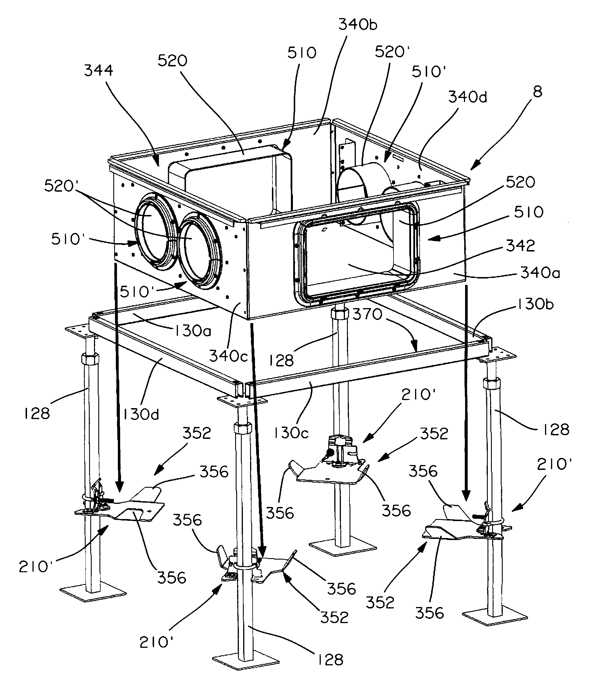
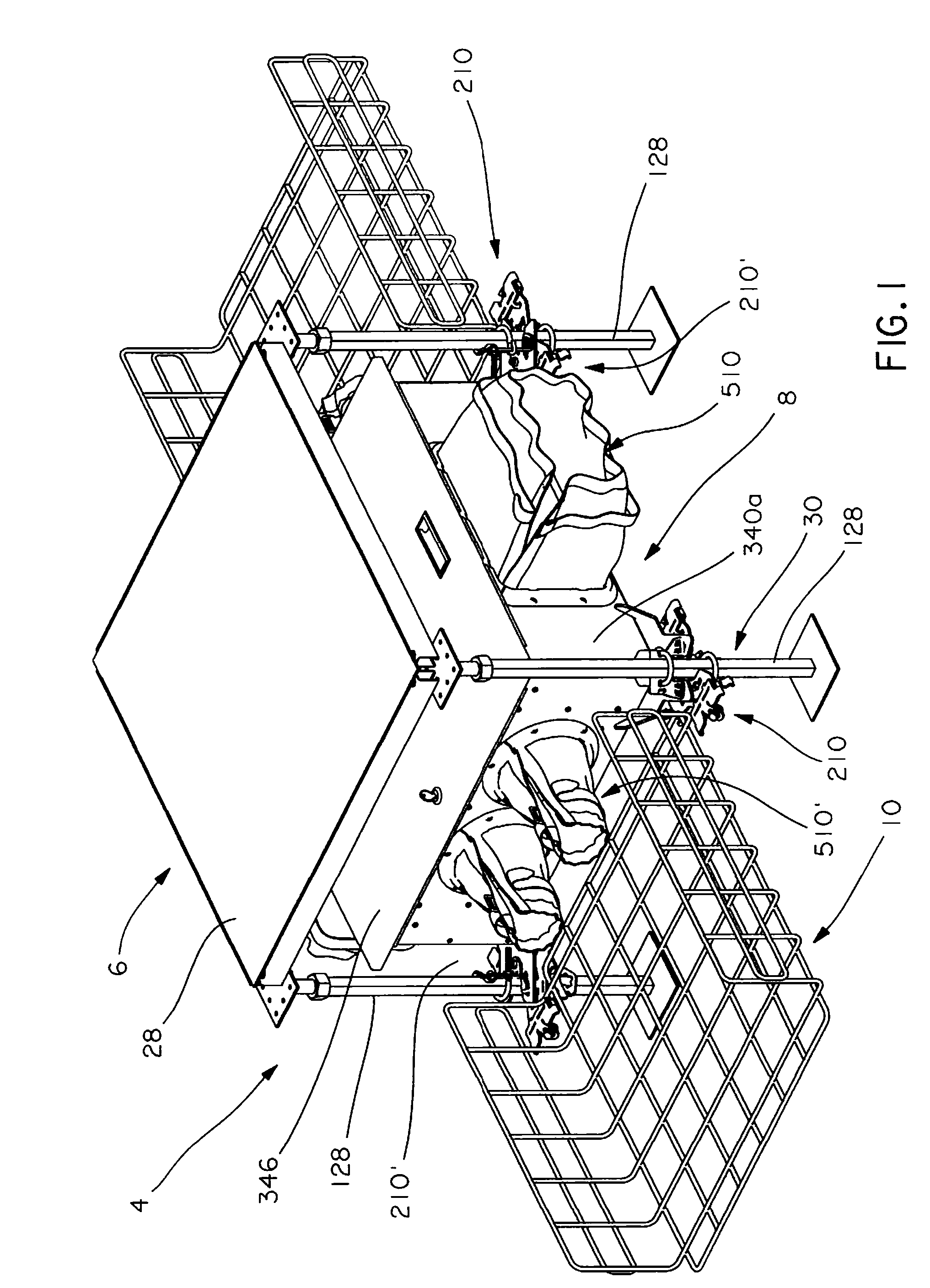
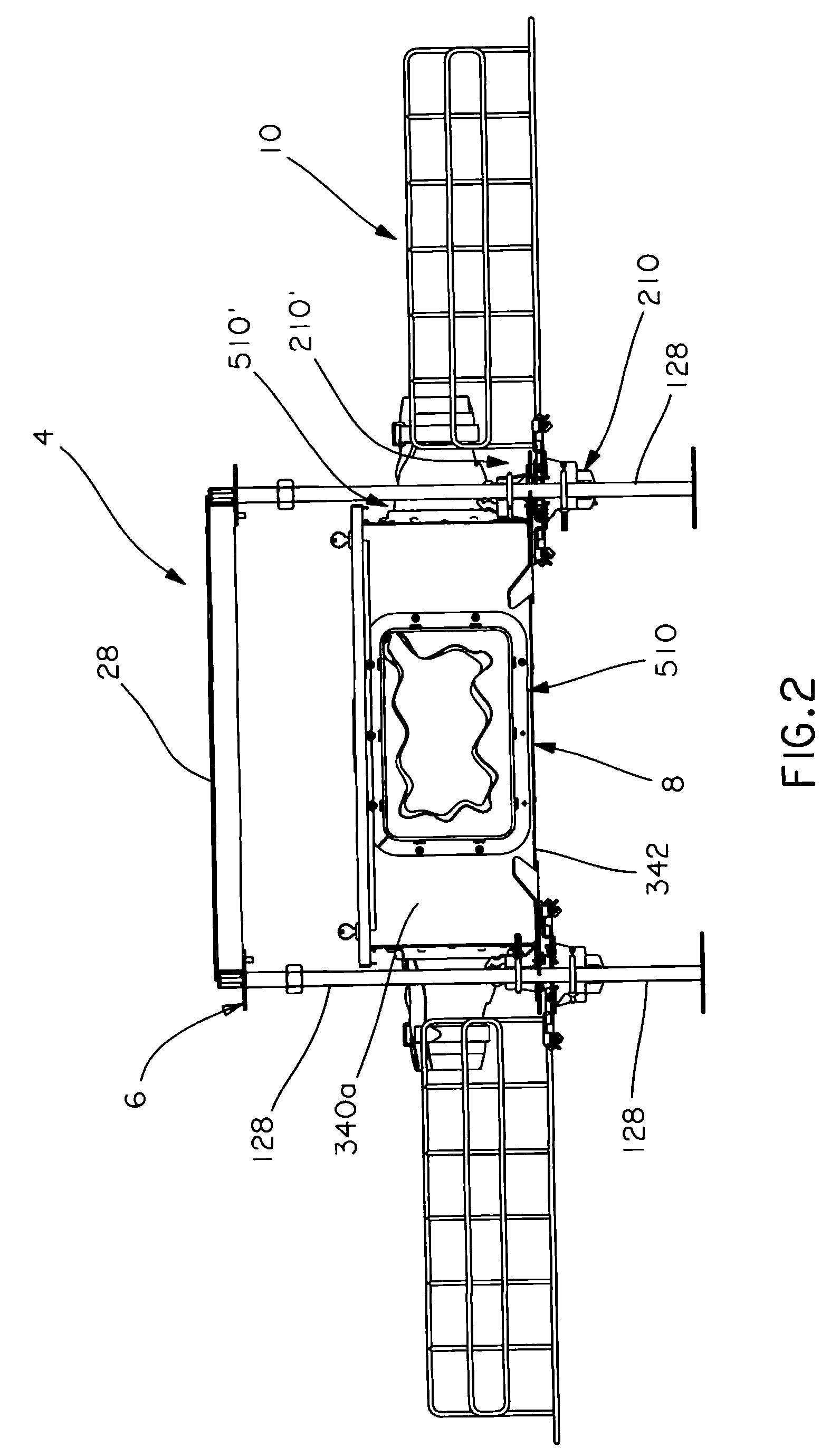
[0077]Referring to FIGS. 1-5 one example of a cable management system 4 is illustrated and is operable to assist with managing communication cables carrying electronic signals between electrical instrumentation (not shown). In the illustrated construction, the cable management system 4 is used with a raised floor grid system 6 (see FIG. 6), which includes raised floor tiles 28 and a support structure 30. The support structure 30 is supported on a lower floor 26 and supports the raised floor tiles 28 above the lower floor 26. For simplicity, only a single raised floor tile 28 and associated support structure 30 are illustrated. In use, an array of raised floor tiles 28 and associated support structures 30 will be utilized (see FIG. 6). Alternatively, the cable management system 4 may be used in applications other than raised floor grid systems to assist with managing communication cables in such applications. The cable management system 4 includes a wire basket pathway system 10 and ...


PUM


Abstract

A cable management system for managing electrical cables in a raised floor grid system is provided. The cable management system includes a cable enclosure including side walls and a base together defining an enclosure cavity. Each of the side walls defines a cable opening and a plurality of bracket openings in communication with the enclosure cavity. The cable management system also includes a sealing assembly installed in each of the cable openings, and a plurality of equipment brackets mountable to the sidewalls via the bracket openings, which are configured to enable mounting of the equipment brackets in vertical and angled orientations. The cable management system further includes a plurality of support brackets connectable to support structure of the raised floor grid system for supporting the cable enclosure on the support structure. The cable enclosure can be installed in the raised floor grid system by removing only a single floor tile.

Description

CROSS-REFERENCE TO RELATED APPLICATIONS[0001]This application is a continuation-in-part of U.S. patent application Ser. No. 11 / 930,376 filed Oct. 31, 2007, which claims the benefit of U.S. Provisional Patent Application No. 60 / 948,071, filed Jul. 5, 2007; and this application is a continuation-in-part of U.S. patent application Ser. No. 11 / 751,716, filed May 22, 2007, the contents of all are hereby incorporated herein by reference.FIELD OF INVENTION[0002]This invention relates generally to the positioning, support, protection, and interconnection of conductive cables, and is particularly directed to wire basket arrangements and cable enclosures for maintaining pathways of conductive cables securely and safely in position in a raised floor grid system.BACKGROUND OF THE INVENTION[0003]The widespread use of electronic systems in business and industry has led to the requirement to route large numbers of cables throughout the work environment. Various types of cable tray assemblies are u...

Claims


Application Information

Patent Timeline
Patent Type & Authority Patents(United States)
IPC IPC(8): E04C2/52
CPCE04F15/0247H02G3/0443H02G3/385H02G3/083H02G3/22H02G3/0608
Inventor BRAVO, REYSWETT, BRETT A.DAVIS, DAVID R.WASZAK, DENNIS J.JOHNSON, RHONDADUKES, JOSEPH ALLENNELSON, KEVIN L.BRZEZNIAK, STANLEY A.
Owner PANDUIT
Why Eureka
Try Eureka