Pressure-measuring device

a technology of pressure measurement and pressure gauge, which is applied in the direction of fluid pressure measurement using elastically deformable gauges, rapid change measurement, instruments, etc., can solve the problems of diaphragm thermal shock sensitivity, distortion of output pressure signal, and impaired pressure measuremen

Inactive Publication Date: 2011-06-07
ROBERT BOSCH GMBH
View PDF14 Cites 19 Cited by
  • Summary
  • Abstract
  • Description
  • Claims
  • Application Information

AI Technical Summary

Benefits of technology

[0004]An example pressure-measuring device according to the present invention may have the advantage that the precision of the pressure measurement is improved, and in particular distortions of the outputted pressure signal are reduced.
[0008]This results in the advantage that the pressure-measuring device is suitable for use in high-precision injection systems in which, in order to control a homogenous combustion in the combustion chamber, which is very sensitive to the quantity of fuel and the time of the injection, the surface under the combustion curve, and thus the combustion heat, is inferred from the curve of the pressure signal. Moreover, the pressure-measuring device can advantageously be used in a research laboratory in order to enable monitoring of the combustion chamber pressure over the entire working cycle during trials of new engines.
[0009]Advantageously, the diaphragm has a radial segment that is oriented generally perpendicular to the axial direction. This enables an advantageous elastic compression of the diaphragm.
[0010]It is advantageous if the diaphragm has a fastening segment that is connected to the force-transmitting segment via the radial segment, and if the diaphragm is connected at least indirectly to the housing at the fastening segment. Here, the diaphragm can be connected at the fastening segment to a sensor cage, or can be connected directly to the housing. The connection can be formed for example by welding, in particular laser welding. The connection of the fastening segment to the housing provides the advantage that an optimized construction of the fastening segment is enabled with respect to the connecting method. For example, the fastening segment can have a relatively large wall thickness in order to enable a reliable connection. In addition, the fastening segment can have a certain extension, in particular in the axial direction, in order to enable a larger tolerance for the positioning of the connection or connecting points.
[0011]Advantageously, the diaphragm may be connected at least indirectly to the housing at the radial segment. Here, the diaphragm can be connected to the sensor cage at the radial segment. This has the advantage that the portion of the temperature-caused change in length of the diaphragm that has an effect on the pressure measurement can be largely reduced or even completely eliminated. For special applications, in particular laboratory applications, this can further improve the precision of the pressure measurement. Depending on the case of application, this may justify the somewhat greater expense involved in the fastening of the diaphragm to the housing, compared to the embodiment having a fastening segment.
[0013]It is also advantageous if one end of the radial segment goes over into a central part of the force-transmitting segment. This has the advantage that the portion of a thermal change in length of the diaphragm that influences the pressure measurement can be greatly reduced or even completely eliminated, making it possible to carry out an adjustment via the design of the force-transmitting segment. These advantages are found in particular in combination with a fastening segment at which the metal diaphragm is connected to a housing or the like.

Problems solved by technology

WO 2006 / 072514 A1 has the disadvantage that the hot combustion gases that occur during each working cycle cause a heating of the steel diaphragm, followed by a cooling of the steel diaphragm, so that the pressure measurement is impaired due to thermal changes in length of the steel diaphragm.
Specifically, the conventional pencil-type glow plug having the integrated pressure sensor has the disadvantage that a distortion of the outputted pressure signal occurs.
However, a certain thermal shock sensitivity can result from the diaphragm.
Due to its thin-walled construction, the diaphragm has relatively low mass, so that the hot combustion chamber gases cause rapid heating of the metal diaphragm.
The thermal changes in length that are caused by this can cause periodic changes in the pre-tension of the force-measuring module.
In particular, during the heating of the diaphragm a certain relaxation can take place in the pre-tensioned force-measuring module, so that a pressure measurement is temporarily not possible, resulting in a distortion of the pressure measurement signal.
Depending on the case of application, this may justify the somewhat greater expense involved in the fastening of the diaphragm to the housing, compared to the embodiment having a fastening segment.

Method used


Image

  • Pressure-measuring device
  • Pressure-measuring device
  • Pressure-measuring device

Examples


Embodiment Construction

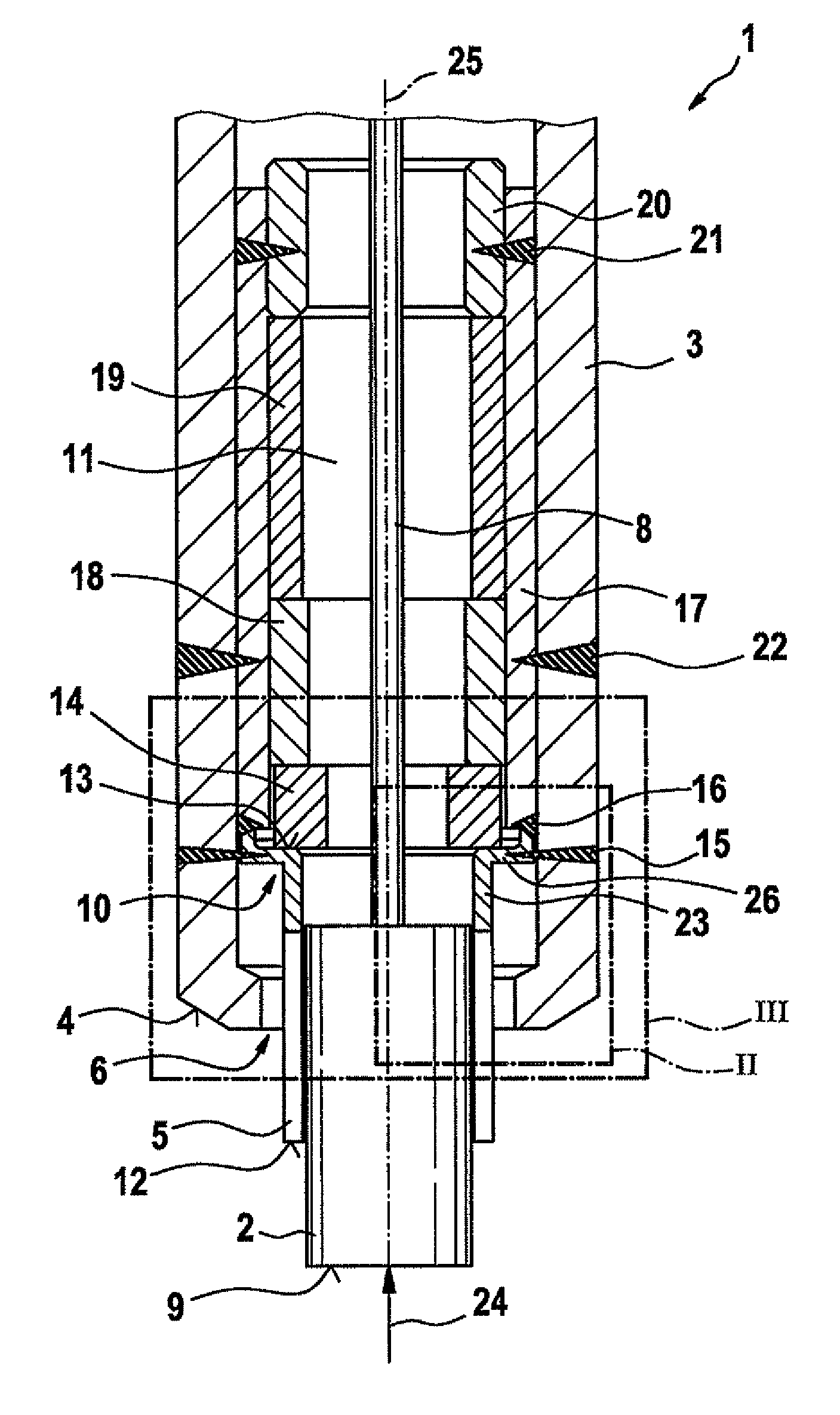
[0018]FIG. 1 shows a first exemplary embodiment of a pressure-measuring device 1, in a schematic, axial sectional representation. Pressure-measuring device 1 is realized as pressure-measuring glow plug 1 for an air-compressing, self-igniting internal combustion engine. In pre-chamber and turbulence chamber engines, a rod-shaped heating element 2 of pressure-measuring glow plug 1 protrudes into the chamber of the internal combustion engine, and in engines having direct injection said heating element protrudes into a combustion chamber of the engine. However, pressure-measuring glow plug 1 according to the present invention is also suitable for other cases of application. In addition, pressure-measuring device 1 can also be realized as a pressure-measuring spark plug or as a pressure-measuring injection valve for mixture-compressing, externally ignited internal combustion engines.

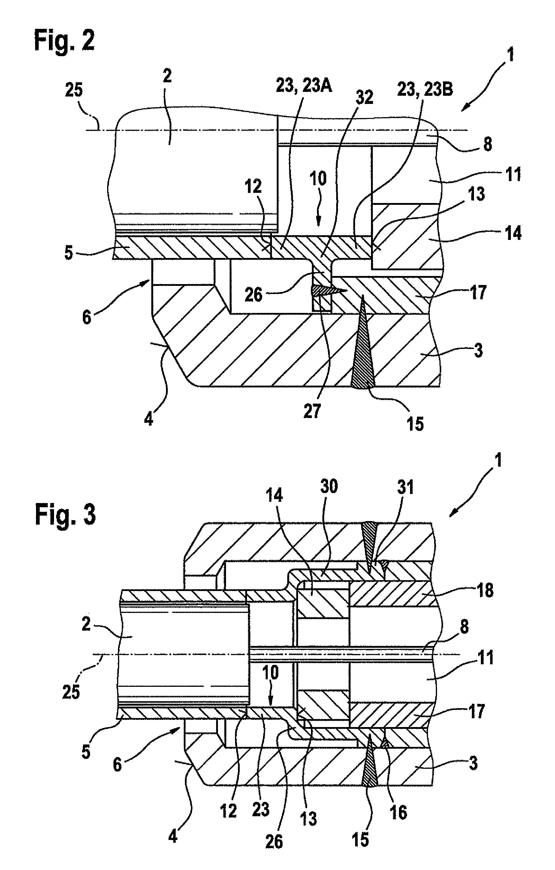
[0019]Pressure-measuring glow plug 1 has a housing 3 that has a sealing cone 4. Rod-shaped heating element...


PUM

PropertyMeasurementUnit
thicknessaaaaaaaaaa
pressureaaaaaaaaaa
spring elasticityaaaaaaaaaa

Abstract

A pressure-measuring device is situated in a chamber of an internal combustion engine. The pressure-measuring device has a housing, a force-transmitting element that protrudes partly from the housing at a chamber-side opening of the housing, and a pressure sensor that is situated in an interior space of the housing. The pressure sensor stands in effective connection to the force-transmitting element. In addition, a diaphragm is provided that seals the interior space of the housing, in which the pressure sensor is situated, against the chamber-side opening. The diaphragm, which is preferably fashioned as a metal diaphragm, has a force-transmitting segment that is oriented in an axial direction of the force-transmitting element. Moreover, the pressure sensor stands in effective connection with the force-transmitting element via the force-transmitting segment of the diaphragm. In this way, there takes place at least a partial compensation of thermally caused changes in length of the diaphragm, caused for example by hot combustion gases, and resulting in periodic impairments of the pressure measurement made by the pressure sensor.

Description

FIELD OF THE INVENTION[0001]The present invention relates to a pressure-measuring device to be situated in a chamber of an internal combustion engine. Specifically, the present invention relates to a pressure-measuring glow plug for disposition in a pre-chamber, turbulence chamber, or combustion chamber of an air-compressing, self-igniting internal combustion engine.BACKGROUND INFORMATION[0002]International Patent Application No. WO 2006 / 072514 A1 describes a pencil-type glow plug has an integrated pressure sensor. The pressure sensor in the conventional pencil-type glow plug is connected to a rod-shaped heating element that is accommodated in movable fashion in the interior of the pencil-type glow plug. A steel diaphragm having a radially symmetrical construction is allocated to the rod-shaped heating element; said steel diaphragm shields a force-measuring element of the combustion chamber pressure sensor against combustion gases, and has a spring elasticity that is a function of i...

Claims


Application Information

Patent Timeline
Patent Type & Authority Patents(United States)
IPC IPC(8): G01L7/08G01L23/22
CPCG01L23/10G01L23/222F23Q2007/002F23Q2007/005
Inventor KERN, CHRISTOPHLANDES, EWGENIJZACH, REIKOSCHUETTOFF, MICHAELKLEINDL, MICHAELDOERING, CHRISTIANSCHOTT, STEFFENSALTIKOV, PAVLO
Owner ROBERT BOSCH GMBH
Why Eureka
Try Eureka