Methods of using colloidal silica based gels

a technology of colloidal silica and gels, which is applied in the direction of sealing/packing, chemistry apparatus and processes, and well accessories, etc., can solve the problems of insufficient gels, reduced hydrocarbon overall yield, and inability to meet the needs of subterranean use in some areas, and achieves the effect of increasing the viscosity of treatment fluids

Active Publication Date: 2011-06-07
HALLIBURTON ENERGY SERVICES INC
View PDF11 Cites 75 Cited by
  • Summary
  • Abstract
  • Description
  • Claims
  • Application Information

AI Technical Summary

Benefits of technology

[0010]Methods that include a method of treating a well bore comprising providing a treatment fluid that comprises a colloidal silica component; optionally providing an activator; introducing the treatment fluid to a portion of a well bore that penetrates a subterranean formation; allowing the treatment fluid to flow into a permeable zone of the subterranean formation; allowing the colloidal silica component of the treatment fluid to be activated by the heat of the formation and / or by contacting the activator; and allowing the activated colloidal silica component to increase the viscosity of the treatment fluid in the permeable zone of the subterranean formation.

Problems solved by technology

This uneven flow of the aqueous displacement fluid through the formations or zones reduces the overall yield of hydrocarbons therefrom.
One drawback to some of the gels that have previously been used as conformance control materials or as other types of subterranean treatments, e.g., sand consolidation treatments, is that those gels may be viewed as unsuitable for subterranean use in some areas according to certain environmental protection guidelines and regulations.
Another drawback is that treatment fluids that comprise conventional polymers and activators may not gel sufficiently at the low temperatures that may be encountered in some subterranean formations, e.g., temperatures below about 20° C. One substance that may meet even rigorous environmental guidelines for use in subterranean operations is colloidal silica.
As such, WO 2004 / 0138381 does not disclose the creation of a new cement sheath or the treatment of an entire well bore to effect an overall reduction in permeability of the most permeable areas of the well bore.

Method used


Image

  • Methods of using colloidal silica based gels
  • Methods of using colloidal silica based gels
  • Methods of using colloidal silica based gels

Examples


example 1

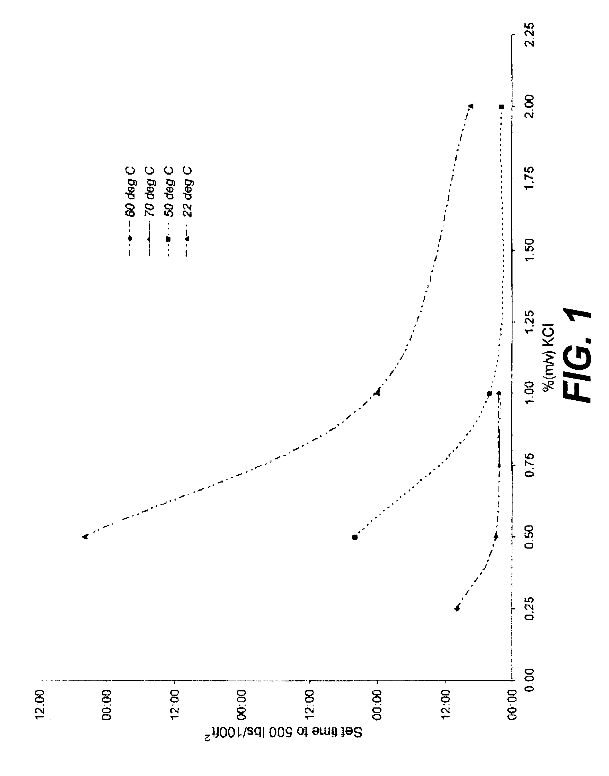
[0045]To determine the effect of temperature and activator concentration on the time required for a mixture of a colloidal silica component and an activator to reach a given viscosity, a base treatment fluid was prepared which comprised an aqueous colloidal silica component. At room temperature, the base treatment fluid had an API plastic viscosity of 7.5 centiPoise (cP) and an API yield point of 1.8 lb / 100 ft2 (0.0879 kg / m2). A potassium chloride activator was added to individual portions of the base treatment fluid in varying amounts to create experimental samples that contained the colloidal silica component and activator in varying relative amounts. The experimental samples were cured at 22° C., 50° C., 70° C., and 80° C., respectively. The gel strength of each sample was measured over time using an apparatus known as the Mini Multiple Analysis Cement Slurry (“MINI MACS™”) analyzer until the gel strength reached a final value of 500 lbs / 100 ft2 (24.41 kg / m2). The MINI MACS™ anal...

example 2

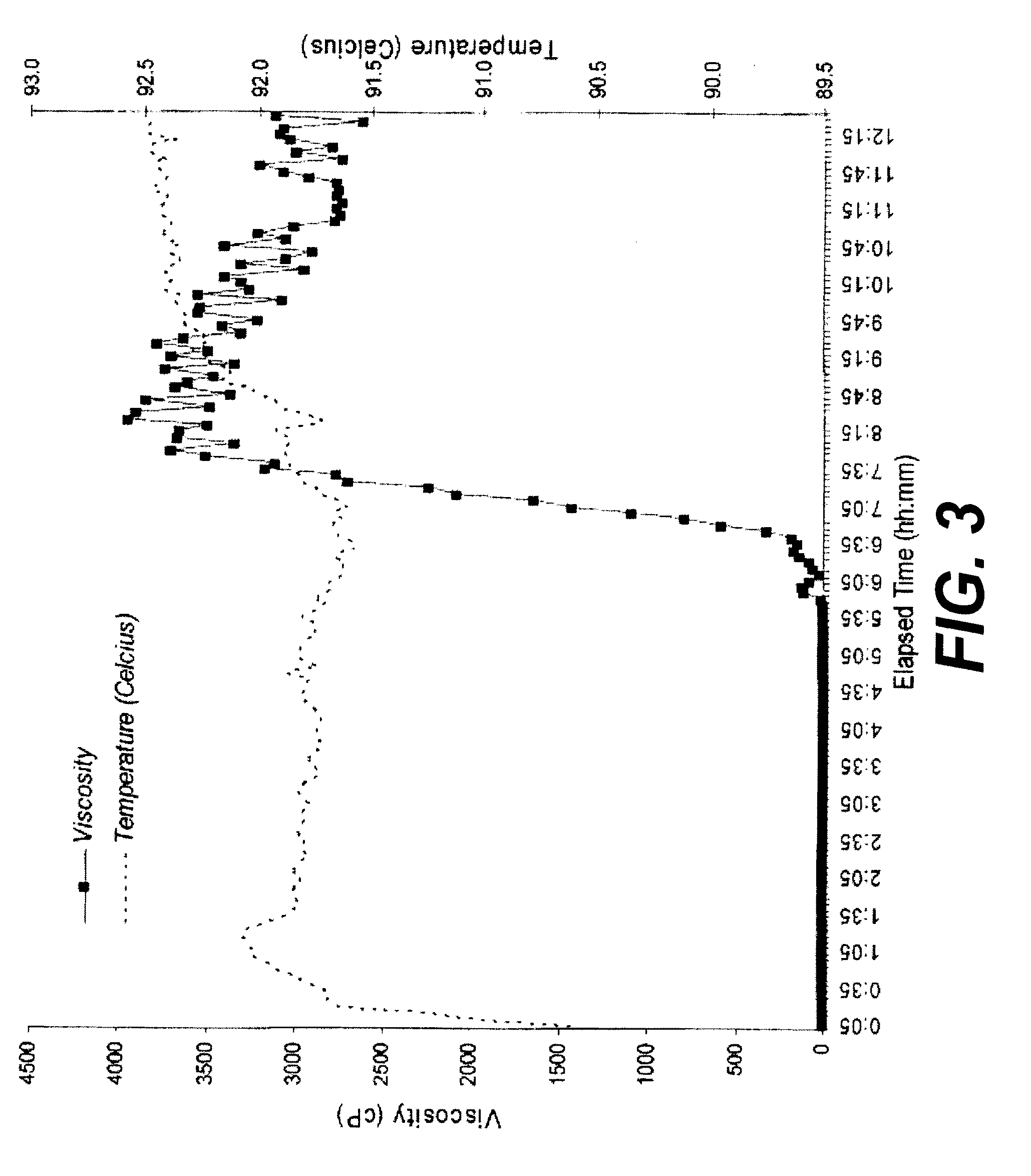
[0046]To demonstrate the ability of a colloidal silica gel to mitigate the migration of a fluid and / or gas through a cement slurry, the gel strength development of a typical cement slurry was tested at conditions typical for a surface casing in a field where pressurized shallow water zones present a drilling hazard. One design parameter commonly used by the industry when dealing with gas migration and shallow water flow is the time it takes for the static gel strength (SGS) of a slurry to increase from 100 to 500 lbs / 100 ft2 (4.88 to 24.41 kg / m2). This time is often referred to as the “transition time.” Ideally this time should be as short as possible in order to minimize the time that gas or fluid can migrate into the cement matrix after placement. The cement slurry that was used in this test comprised a class C cement, the colloidal silica commercially available under the trade name FDP-C725-04, a potassium chloride activator, and other cementing chemicals such as a fluid loss con...

example 3

[0047]In order to determine if the pore space of a typical formation might be blocked by a treatment fluid of the present invention, such that the pore space was substantially impermeable after treatment, the following experiment was performed. In addition, this test was designed to determine whether viscosified treatment fluids of the present invention might be able to withstand pressures of the type that may be encountered across a formation core having high permeability. Bentheim sandstone core was selected for this experiment due to the relatively high permeability of this type of core. The Bentheim sandstone core that was used was substantially clay free, homogeneous, and had a porosity of about 22%. The core measured 3.70 cm in diameter, 5.78 cm in length, and had a permeability of 846 milliDarcies. The pore volume of the cores was determined to be 13.67 mL.

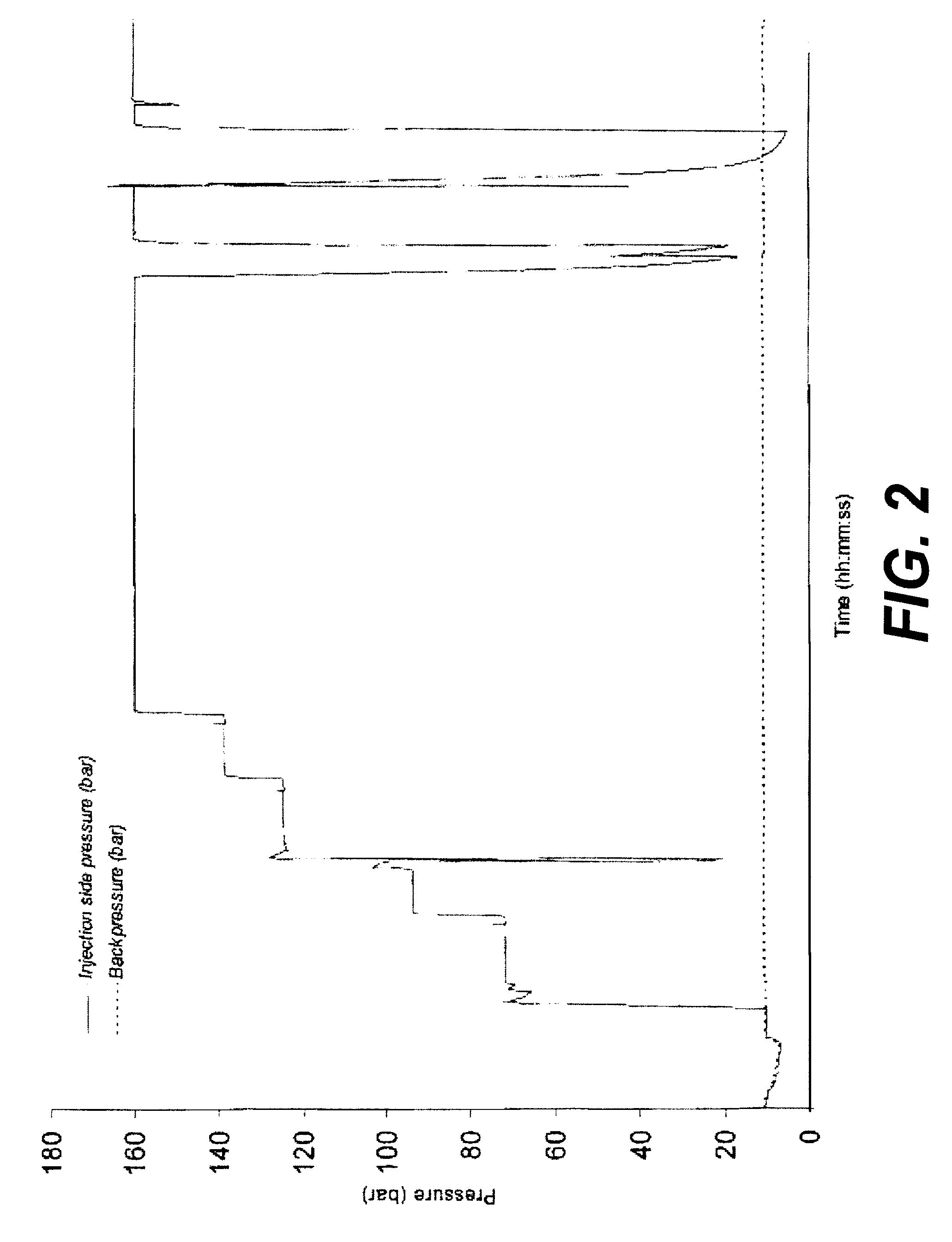
[0048]After the core was mounted in a Hassler cell core holder and vacuumed, the core was placed in a vertical orientatio...


PUM

PropertyMeasurementUnit
temperaturesaaaaaaaaaa
diameteraaaaaaaaaa
particle sizeaaaaaaaaaa

Abstract

Methods of controlling flow through a subterranean formation may include providing a cement slurry, a colloidal silica, and an activator. The methods may include introducing the cement slurry, the colloidal silica, and the activator into a portion of a well bore that penetrates a subterranean formation The methods may include allowing the cement slurry, colloidal silica, and activator to remain static.

Description

CROSS-REFERENCE TO RELATED APPLICATION[0001]This application is a continuation of PCT Application No. PCT / GB2007 / 003469, filed Sep. 13, 2007, the disclosure of which are hereby incorporated by reference in its entirety.TECHNICAL FIELD[0002]The present invention generally relates to the use of colloidal silica in subterranean treatments. More specifically, the present invention relates to the use of treatment fluids that comprise a colloidal silica component. In another aspect, the present invention relates to subterranean cements comprising a treatment fluid that comprises a colloidal silica component. The methods of the present invention may be particularly useful in water injection wells, gas injection wells, and hydrocarbon wells and recovery operations.BACKGROUND ART[0003]When hydrocarbons are produced from wells that penetrate hydrocarbon producing formations or zones, water often accompanies the hydrocarbons, particularly as the wells mature in time. The water can be the resul...

Claims


Application Information

Patent Timeline
Patent Type & Authority Patents(United States)
IPC IPC(8): E21B33/138
CPCC04B28/02C09K8/467C09K8/5045C09K8/845C04B14/062C04B22/06C04B22/085C04B22/124C04B22/14
Inventor LENDE, GUNNAROLAUSSEN, STEIN
Owner HALLIBURTON ENERGY SERVICES INC
Why Eureka
Try Eureka