Safety retaining system for large industrial fan

a safety retaining system and industrial fan technology, applied in the direction of pump components, pump control, non-positive displacement fluid engine, etc., can solve the problems of large amount of smoke or particulate air pollution, inability or cost-effective to run air conditioning systems, and inability to reduce the ambient air temperature inside the building

Inactive Publication Date: 2011-06-07
MACROAIR TECH
View PDF57 Cites 36 Cited by
  • Summary
  • Abstract
  • Description
  • Claims
  • Application Information

AI Technical Summary

Benefits of technology

[0010]The aforementioned needs are satisfied by the fan assembly of the present invention which, in one particular implementation, comprises a fan assembly for a fan having an assembled diameter of at least five feet wherein the fan assembly comprises a motor assembly that mounts to a surface of a building wherein the motor assembly includes a fan motor having a shaft that is rotated by the fan motor and a hub that is coupled with the fan motor shaft and rotates in response to rotation of the fan motor shaft wherein the hub is configured to receive a plurality of fan blades having length in excess of five feet such that rotation of the hub results in rotation of the fan blades. In this implementation, the motor assembly and the rotor define an interface and a retaining system is mounted in the interface defined by the motor assembly and the hub. The retaining system couples the rotor to the motor assembly such that in the event of the motor shaft breaking or the hub otherwise disengages from the shaft, the hub is inhibited from falling from the motor assembly.
[0011]In one particular implementation, the retaining system is positioned between the rotor and the fan motor about the shaft of the fan mot

Problems solved by technology

In some industrial applications, it is not possible or cost effective to run air conditioning systems and, in these circumstances, large fans that produce a substantial air flow can significantly reduce the ambient air temperature inside the building.
In this environment, there can be a large amount of smoke or particulate air pollution necessitating constant access to fresh air for the workers therein.
To achieve this, either a highly expensive air exchange system would have to be installed on the building or, more commonly, the doors and windows of the buildings are left open to provide venting for the smoke and gas by-products of the welding processes.
Air exchange systems are often very expensive, but, in many locations, leaving the doors and windows open is also uncomfortable.
For example, in hot weather, the inside of the building may become uncomfortably hot.
While th

Method used


Image

  • Safety retaining system for large industrial fan
  • Safety retaining system for large industrial fan
  • Safety retaining system for large industrial fan

Examples


Embodiment Construction

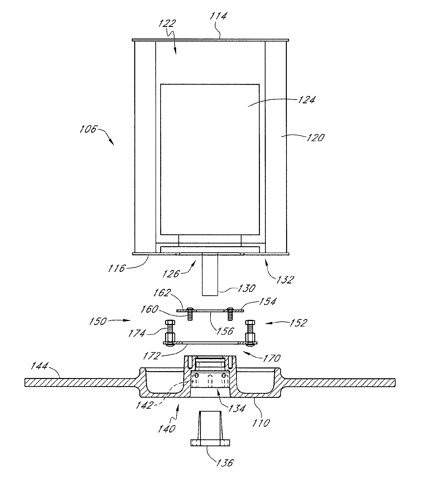
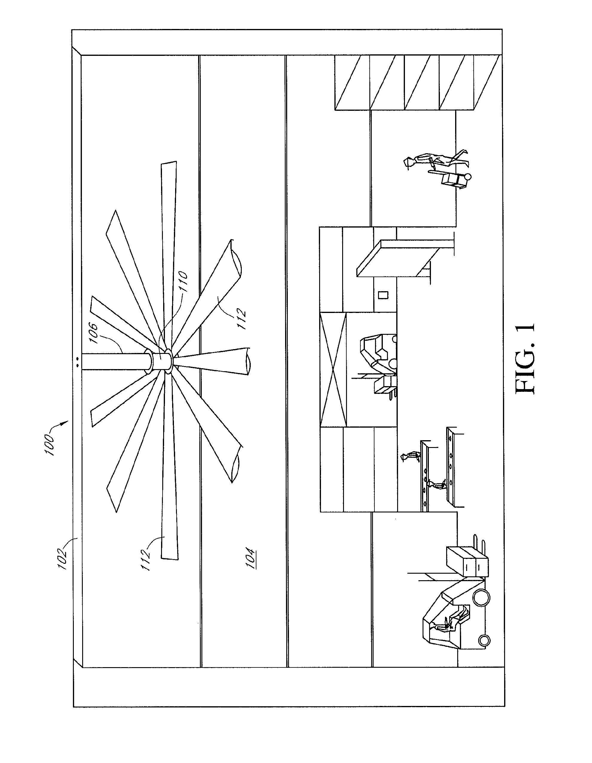
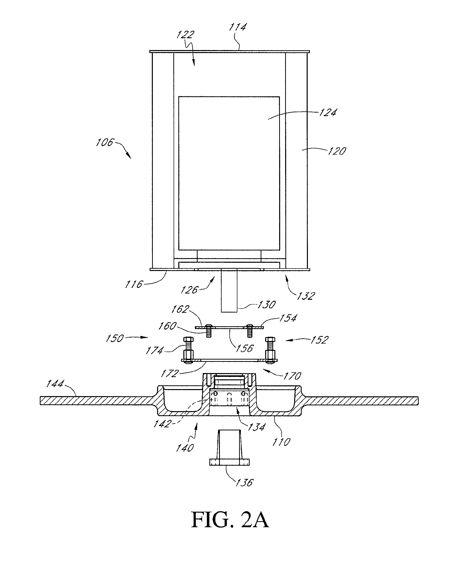
[0019]Reference will now be made to the drawings wherein like numerals refer to like parts throughout. FIG. 1 illustrates a fan assembly 100 mounted to an interior wall 102 of a building 104. In this particular implementation, the fan assembly is shown as being mounted to the ceiling 102, however, it will be appreciated that large industrial-type cooling fans can also be mounted to side walls of the building without departing from the spirit of the present invention. As is generally shown in FIG. 1, the fan assembly includes a motor mount 106 that attaches the fan to the interior wall 102 of the building 104, a hub 110 which is rotatably engaged with the motor mount 106 and a plurality of fan blades 112 that extend radially outward from the hub 110. In this particular implementation, the fan blades extend generally a distance of approximately at least five feet from the hub and, more particularly, at least 10 feet, and the fan preferably rotates at a speed that induces air to be cir...


PUM


Abstract

A securing system for a fan assembly. The securing system includes a first member which attaches to a motor mount and a second member which attaches to the hub of the fan assembly. The first member is interposed between the hub and the second member such that should the shaft of the motor break, the first and second members engage with one another and inhibit the fan assembly from falling away from the motor mount.

Description

CROSS-REFERENCE TO RELATED APPLICATIONS[0001]This application claims the benefit of U.S. Provisional Application No. 60 / 792,309 filed Apr. 14, 2006 entitled Safety Retaining System for Large Industrial Fan which is hereby incorporated in its entirety herein.BACKGROUND OF THE INVENTION[0002]1. Field of the Invention[0003]The present invention relates to industrial fans, such as industrial ceiling fans and, in particular, involves a safety system that inhibits the fan from falling as a result of motor shaft failure.[0004]2. Description of the Related Art[0005]Fans are commonly used appliances for cooling the interiors of buildings. In some industrial applications, very large fans with blades having diameters in excess of ten feet are often used to cool the interior of buildings. In some industrial applications, it is not possible or cost effective to run air conditioning systems and, in these circumstances, large fans that produce a substantial air flow can significantly reduce the am...

Claims


Application Information

Patent Timeline
IPC IPC(8): F04D29/64
CPCF04D25/088F04D29/601F04D27/008F04D29/646F04D27/0292
Inventor BOYD, WALTER KENTBOYD, EDWARD KENT
Owner MACROAIR TECH
Why Eureka
Try Eureka