

Reusable substrate for DNA microarray production
a dna microarray and substrate technology, applied in the direction of isotope separation, sequential/parallax process reactions, electrolysis, etc., can solve the problems of inability to purify, limited quality control,
- Summary
- Abstract
- Description
- Claims
- Application Information
AI Technical Summary
Benefits of technology
Problems solved by technology
Method used
Image

Examples
example 1
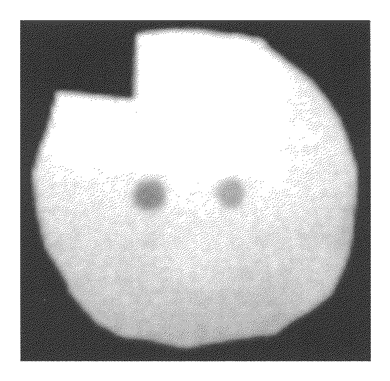
Coupling of Two Different Fluorescent Dyes at Two Different Positions of the Porous Membrane
[0129]Two different fluorescent dyes are coupled at two different positions of the substrate to generated two different fluorescent spots. In this example the coupling of a CY5 and a CY3 fluorescent dye is described. For this experiment, a selfmade reaction chamber comprising an electrode array with two gold electrodes, an inorganic porous membrane, standard DNA synthesis reagents, phosphoramidites of the fluorescent dyes and a buffer solution to electrochemically generate an acid media at the activated electrode is used.
[0130]The porous membrane is placed in proximity to the electrodes in the reaction chamber. Because the porous membrane itself has only binding sites without any protective groups, 5′-DMT-T-3′-phosphoramidites are coupled to the porous membrane as a starting group. For this purpose, the 5′-DMT-T-3′-phosphoramidites together with an activator are filled into the chamber to rea...
example 2
Synthesis of Two Different Oligonucleotides at Two Different Positions on a Membrane and Hybridization with Complementary Target Oligonucleotides
[0133]Two different oligonucleotides are synthesized at two different positions of the substrate using the setup of example 1. In this example, the synthesis of a (dA)15-mer (SEQ ID NO: 3) and a (T)15-mer (SEQ ID NO: 4) oligonucleotide at two different positions of a porous membrane is described.
[0134]The porous membrane is placed in proximity to the electrodes in the reaction chamber. At the beginning, a T-phosphoramidite is coupled to the functional groups of the membrane and stabilized afterwards like explained in example 1. Next, an electrical potential is applied to the first electrode to cleave the protecting groups in proximity to the activated electrode. After the buffer solution is rinsed out of the chamber, the next 5′-DMT-T-3′-phosphoramidite with an activator is filled into the chamber to react with the deprotected binding sites...
example 3
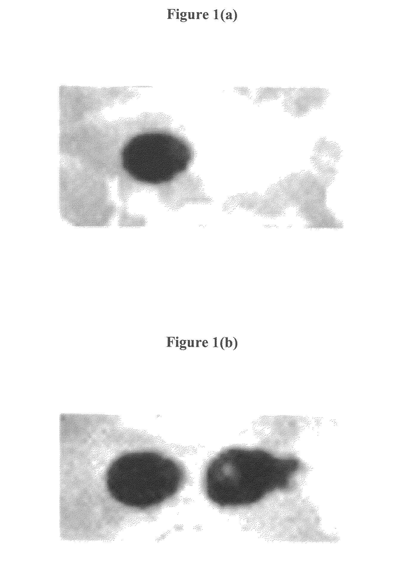
Coupling of Two Different Fluorescent Dyes at Two Different Positions of the Porous Membrane
[0137]Two different fluorescent dyes (CY5 and a CY3) were coupled at two different positions of the substrate to generated two different fluorescent spots. For this experiment, a self-made reaction chamber (volume 400 μl, height 0.9 mm) comprising an electrode array with two gold electrodes, an inorganic porous membrane, standard DNA synthesis reagents (containing DMT-phosphoramidites from Roth and Proligo, activator DCI, and capping reagents from Proligo, acetonitrile from Promochem, oxidizing reagent from Applied Biosystems), phosphoramidites of the fluorescent dyes (from Amersham Biosciences) and an electrochemically active buffer solution to electrochemically generate an acid media at the activated electrode were used. The self-made reaction chamber was made out of PEEK material with the two gold electrodes (diameter of each electrodes is 1.8 mm arranged with a distance of 3 mm) integrate...
PUM
| Property | Measurement | Unit |
|---|---|---|
| pore size | aaaaa | aaaaa |
| pore size | aaaaa | aaaaa |
| pore size | aaaaa | aaaaa |
Abstract
Description
Claims
Application Information