Pad clip for disc brake

a technology of disc brakes and pads, applied in the field of pads, can solve the problems of poor material yield, increased unused portion of metal plates constituting materials, poor blanking performance, etc., and achieve the effect of excellent blanking performance and low cos

Active Publication Date: 2011-06-14
AKEBONO BRAKE IND CO LTD
View PDF15 Cites 5 Cited by
  • Summary
  • Abstract
  • Description
  • Claims
  • Application Information

AI Technical Summary

Benefits of technology

[0020]One or more embodiments of the present invention provide a pad clip which can stabilize attitudes of an outer pad and an inner pad and is inexpensive and excellent in a blanking performance (yield of material).
[0028]According to the pad clip for the disc brake as described above, there is provided a structure which can stabilize attitudes of the outer pad and the inner pad and is inexpensive and excellent in blanking performance (yield of material). That is, the two pads can stabilize the attitudes regardless of braking time, non braking time since the both end portions in the rotational direction are elastically pressed by the respective press pieces. Further, the pad clip is formed by bending a single sheet of a metal plate, and therefore, the pad clip can be produced more inexpensively than a structure of coupling two sheets of metals as shown by FIG. 10 (A).
[0030]In contrast thereto, in the case of the example, the respective press pieces are formed by being folded to bend from the both end portions of the engaging plate portion, and therefore, in comparison with a structure of folding back a front half portion as an elastic engaging portion as shown by FIG. 10 (B) and FIG. 13, amounts of projecting portions in correspondence with the respective press pieces in the state of the material plate can be reduced and the blanking performance can be improved.
[0031]Further, if the both end portions in the rotational direction of the rotor of the respective press pieces are folded to bend in directions in which the more remote from the center portion, the more directed to the outer sides in the radial direction, rigidities of the respective press pieces can be ensured, and a sliding resistance accompanied by displacements in the axial direction of the rotor of the two pads can be restrained by reducing areas of portions thereof brought into contact with the two pads. Thereby, the attitudes of the two pads can further be stabilized.
[0032]Further, it is preferable to reduce an area of the contact portion (preferably, near to point contact) in order to stabilize the state of bringing the respective press pieces and end edges of the two pads into contact with each other without one side contact regardless of a behavior of the two pads, progress of wear of linings constituting the two pads or occurrence of uneven wear. Therefore, the area of the contact portion can further be reduced, if the respective press pieces are bent to project to the inner side in the radial direction at the center portion in the rotational direction of the rotor.

Problems solved by technology

As a result, an unused portion of the metal plate constituting the material is increased (blanking performance is not good=yield of material is poor).
Therefore, a dimension of the material plate before being folded back is increased, and the blanking performance (yield) is further deteriorated.
Therefore, in punching a material plate from a metal plate constituting a material, it is unavoidable that the interval between contiguous material plates is increased, and the blanking performance (yield) is deteriorated.

Method used


Image

  • Pad clip for disc brake
  • Pad clip for disc brake
  • Pad clip for disc brake

Examples


first exemplary embodiment

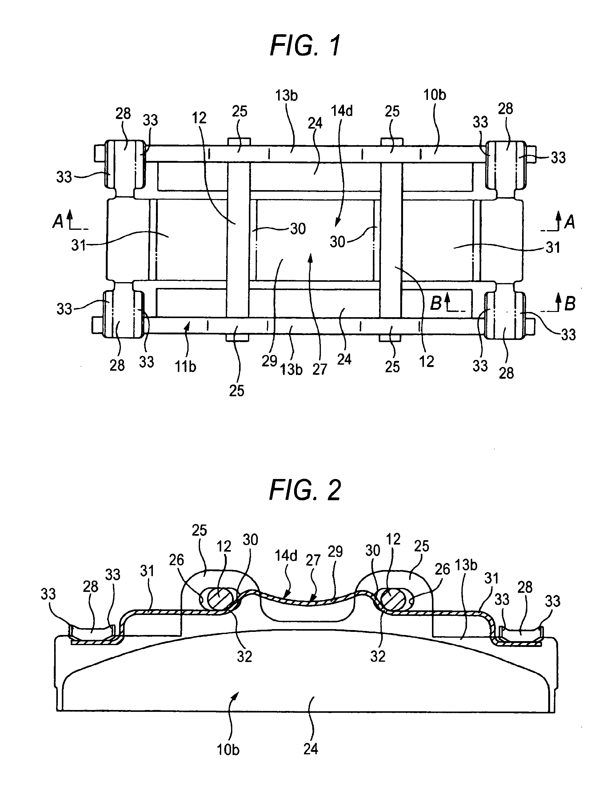
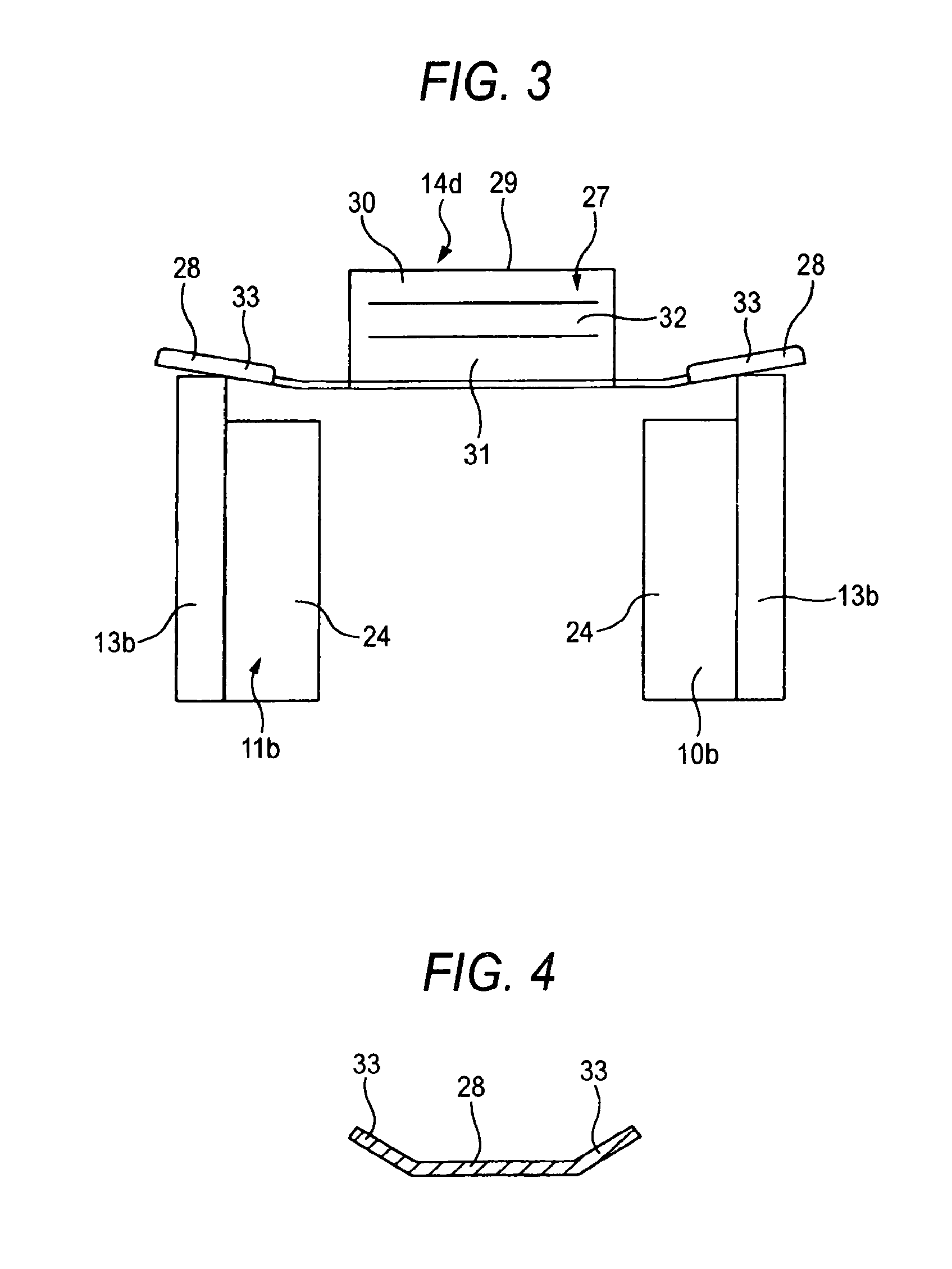
[0048]FIG. 1 through FIG. 4 show a first exemplary embodiment of the invention. Illustration and explanation of duplicated portions with the background art structures shown in FIG. 8, 9 are omitted or simplified and an explanation will be mainly given to a characteristic portion of the exemplary embodiments as follows.

[0049]In the first exemplary embodiment, respective two portions of projected portions 25, 25 projected to an outer side in a radial direction of the rotor 2 (refer to FIG. 8, 9, 11, 12) are formed at outer peripheral edges of middle portions in a rotational direction of pressure plates 13b, 13b constituting the outer pad 10b and the inner pad 11b. Further, through holes 26, 26 are respectively formed at the respective projected portions 25, 25. Further, at a portion proximate to an outer side in the radial direction of the outer peripheral edge of the rotor 2, pins 12, 12 constituting a caliper, not illustrated, and provided in a state of being made to bridge an outer...

second exemplary embodiment

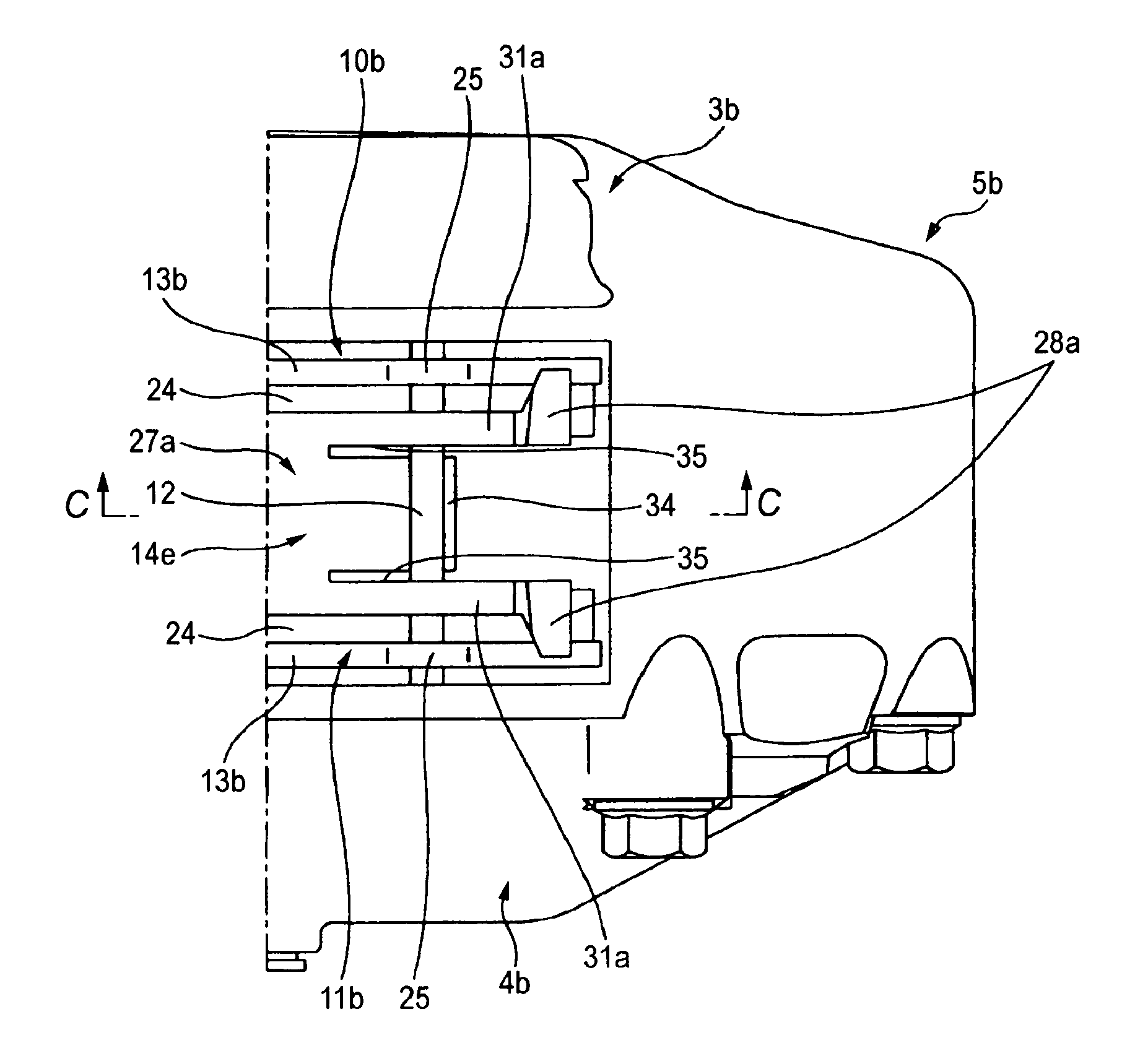
[0059]FIGS. 5 through 7 show a second exemplary embodiment of the invention. A pad clip 14e of the second exemplary embodiment is formed with arm portions 31a, 31a provided with press pieces 28a, 28a at front end portions thereof respectively at positions remote from each other in the axial direction of the rotor 2 (refer to FIG. 8, 9, 11, 12). That is, the arm portions 31a, 31a are constituted by both end portions in the axial directions of an engaging plate portion 27a and portions proximate to both ends in the rotational direction of the rotor 2 for engaging the pad clip 14e with the pin 12 made to bridge an outer body portion 3b and an inner body portion 4b constituting a caliper 5b. Further, locking hook portions 34 are respectively formed at a middle portion in the axial direction and both end portions in the rotational direction of the rotor 2 of the engaging plate portion 27a. Therefore, the respective locking hook portions 34 are arranged between the respective arm portions...

third exemplary embodiment

[0065]Although according to the above-described respective exemplary embodiments, an explanation has been given of a case of applying the invention to the structure of hanging the outer pad and the inner pad by the pin made to bridge the outer body portion and the inner body portion, the invention is applicable also to a structure of supporting the two pads 10a, 11a by support members of the locking pins 36, 36 or the like formed at the two body portions 3a, 4a as in the second example of the background art structure shown in FIGS. 11 through 13. Further, in order to stabilize a state of bringing the respective elastic pieces and the end edges of the pressure plates into contact with each other regardless of a behavior of the two pads, progress of wear of the linings or occurrence of uneven wear without one side contact, the respective press pieces may be bent to project to the inner side in the radial direction at the center portion in the rotational direction of the rotor.


PUM


Abstract

The pad clip 14d is arranged between pins 12, 12 made to bridge an outer body portion and an inner body portion constituting a caliper and the two pads 10b, 11b. An engaging plate portion 27 is engaged with the respective pins 12, 12 without play. Press pieces 28, 28 formed by folding to bend both end portions in a rotational direction of the engaging plate portion in directions in which the more proximate to the two pads 10b, 11b, the more directed to an outer side in a radial direction are brought into elastic contact with outer peripheral edges of both end portions in a rotational direction of pressure plates 13b, 13b of the two pads 10b, 11b. Thereby, amounts of projecting portions in correspondence with the respective press pieces 28, 28 in a state of a material plate before being folded to bend from the engaging plate portion 27 can be restrained.

Description

[0001]This application claims foreign priority from Japanese Patent Application No. 2006-174780, filed on Jun. 26, 2006, the entire contents of which are hereby incorporated by reference.BACKGROUND OF THE INVENTION[0002]1. Field of the Invention[0003]The present invention relates to a pad clip, used in a disc brake of a vehicle, for preventing a pad from being rattled in non braking time and pulling the pad apart from a side face of a rotor in accordance with releasing braking.[0004]2. Related Art[0005]A disc brake is widely used for braking a vehicle. In braking by the disc brake, a pair of pads arranged on both sides in an axial direction of a rotor rotated along with a wheel is pressed to both side faces of the rotor by pistons. Although there are known such disc brakes having various structures in a background art, an opposed piston type disc brake provided with pistons on both sides of the rotor in a state of being opposed to each other achieves a stable brake force. Therefore,...

Claims


Application Information

Patent Timeline
Patent Type & Authority Patents(United States)
IPC IPC(8): F16D65/40
CPCF16D65/0977F16D2055/007
Inventor MORIO, TAKEFUMISASAKI, TAKAAKI
Owner AKEBONO BRAKE IND CO LTD
Why Eureka
Try Eureka